
User manual

TMCM-110-42 Manual 6
Copyright © 2005, TRINAMIC Motion Control GmbH & Co. KG
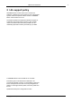
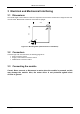
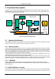
Connector 2
Connector 1
Connector 3
Pin 1
Pin 1
Pin 1
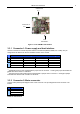
Figure 3.2: The TMCM-110-42 module
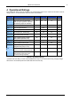
3.3.1 Connector 1: Power supply and host interface
Use this connector to connect the power and the host interface (RS232, RS485, IIC or CAN). The pin
assignments are different for the four available versions of the module.
Function
Pin
RS232 RS485
1)
IIC CAN
2)
1 GND GND GND GND
2 +7..34V DC +7..34V DC +7..34V DC +7..34V DC
3 GND GND GND GND
4 RxD RS485+ SCL CAN +
5 TxD RS485 - SDA CAN -
Table 3.1: Connector 1
1)
The RS485 version is also equipped with a jumper next to connector 1. Closing this jumper terminates the
RS485 bus with a resistor of 100 ohms.
2)
The CAN version of this module is also equipped with a jumper next to connector 1. Closing this jumper
terminates the CAN bus with a resistor of 120 ohms.
3.3.2 Connector 2: Motor connector
Connect a two-phase bipolar stepper motor to this connector. The pin assignment of this connector is as
follows:
Pin Function
1 Phase A1
2 Phase A2
3 Phase B1
4 Phase B2
Table 3.2: Connector 2