
User manual

TMCM-110-42 Manual 7
Copyright © 2005, TRINAMIC Motion Control GmbH & Co. KG
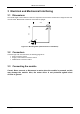
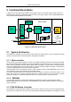
3.3.3 Connector 3: Additional I/O
All other inputs and outputs of the module can be connected here. These are the limit switches, a general
purpose input and a general purpose output. The limit switch inputs are equipped with internal pull-up
resistors, so they have to be connected to GND via normally closed switches. The general purpose input can
either be used as a digital TTL input or as an analogue input (0..5V). The general purpose output is an open
collector output for a maximum current of 100mA. A freewheeling diode is also included so that e.g. a relay
or a coil can be connected directly. Please note that the freewheeling diode is connected to the supply
voltage and not to +5V, so when using e.g. a relay that is connected to +5V a freewheeling diode must be
connected externally.
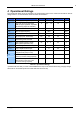
The pin assignment of this connector is as follows:
Pin Name Function
1 StopL Left limit switch input (integrated 10K pullup to 5V)
2 StopR Left limit switch input (integrated 10K pullup to 5V)
3 GND Signal Ground
4
GPO General purpose output 0
(open collector, max. 100mA, max. 40V, 1K pullup to 5V integrated)
5 VDD VDD (same as connector 1, pin 2)
6 GND Signal Ground
7 GPI General purpose input (Analog / Digital)
8 +5V +5V DC output (max. 20mA)
Table 3.3: Connector 3
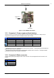
3.3.4 ISP Connector
The 6-way (2x3) header on the module is the connector for an Atmel ISP programmer which can be used to
program the CPU directly. This is to be done by Trinamic only. The ISP connector is not to be used by the
user. Always leave this connector open.
3.4 Activity LED
The TMCM-110-42 module is equipped with an LED. Some TMCM-110-42 modules are equipped with a
yellow LED and some other TMCM-110-42 modules are equipped with a red LED.
During normal operation this LED flashes. After resetting the configuration EEPROM it maybe takes some
seconds before the LED starts flashing.
When the operating system is being downloaded to the module the LED lights steadily.