
User manual

TMCM-110-42 Manual 8
Copyright © 2005, TRINAMIC Motion Control GmbH & Co. KG
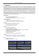
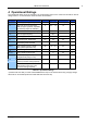
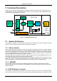
4 Operational Ratings
The operational ratings show the intended / the characteristic range for the values and should be used as
design values. In no case shall the maximum values be exceeded.
Symbol Parameter Min Typ Max Unit
V
S
Power supply voltage for operation 7 12 ... 30 34*) V
I
COIL
Motor coil current for sine wave
peak (chopper regulated, adjustable
via software) (adjust via Software)
0 0.4 … 1.5 1.5 A
I
MC
Continuous motor current (RMS) 0 0.3... 1.1 1.1 A
f
CHOP
Motor chopper frequency 36.8 kHz
I
S
Power supply current << I
COIL
1.4 * I
COIL
A
U
+5V
+5V output (max. 20mA load) 4.8 5.0 5.2 V
V
GPO
Open collector output, max. 100mA,
freewheeling diode included
V
S
V
V
INPROT
Input voltage for StopL, StopR,
GPI0 (internal protection, DC)
-24 0 … 5 24 V
V
ANA
GPI0 analog measurement range 0 ... 5 V
V
STOPLO
StopL, StopR low level input 0 0.9 V
V
STOPHI
StopL, StopR high level input
(integrated 10k pullup to +5V)
1.9 5 V
Environment temperature at rated
current (no forced cooling required)
-40 45 °C T
ENV
Environment temperature at 80% of
rated current or 50% duty cycle
(no forced cooling required)
-40 60 °C
Table 4.1: Operational Ratings
*) Please make sure that you have a TMC246A-PA driver chip on the module when using a supply voltage
above 28.5V. All modules produced in 2006 and later have this chip.