
User manual

PD-1140 Hardware Manual (Rev. 1.01 / 2012-JUL-30) 12
www.trinamic.com
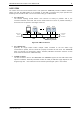
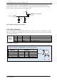
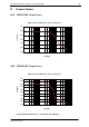
4.3.2 Multipurpose I/O Connector
An 8pin JST PH-series 2mm pitch single row connector is available for all multipurpose inputs and
outputs.
8
1
Pin
Label
Direction
Description
1
GND
Power (GND)
System and signal ground
2
VDD
Power (Supply)
VDD, connected to VDD pin of the power and
communication connector
3
OUT_1
Output
Open-drain output (max. 1A)
Integrated freewheeling diode to VDD
4
OUT_0
Output
+5V supply output (max. 100mA)
Can be switched on/off in software
5
AIN_0
Input
Dedicated analog input,
Input voltage range: 0..+10V
Resolution: 12bit (0..4095)
6
IN_0,
STOP_L,
ENC_A
Input
General purpose digital input (+24V compatible)
Alternate function 1: left stop switch input
Alternate function 2: external incremental
encoder channel A input
7
IN_1,
STOP_R,
ENC_B
Input
General purpose digital input (+24V compatible)
Alternate function 1: right stop switch input
Alternate function 2: external incremental
encoder channel B input
8
IN_2,
HOME,
ENC_N
Input
General purpose digital input (+24V compatible)
Alternate function 1: home switch input
Alternate function 2: external incremental
encoder index / zero channel input
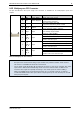
Table 4.4 Multipurpose I/O connector
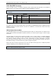
Note:
- All inputs have resistor based voltage input dividers with protection diodes. These resistors
also ensure a valid GND level when left unconnected.
- For all digital inputs (IN_0, IN_1, IN_2) a 2k2 pull-up resistor to +5V can be activated. Then these
inputs have a default (unconnected) logic level of 1 and an external switch to GND can be
connected. This might be especially interesting in case these inputs are used as STOP_L /
STOP_R and HOME switch inputs (alternate function 1) or as encoder input for an external
incremental A/B/N encoder with open-collector outputs (pull-ups are not necessary for encoder
with push-pull outputs).