MODULE Module for Stepper Motors TMCM-3230 TMCL™ Firmware Manual Firmware Version V1.07 | Document Revision V1.05 • 2017-OCT-10 The TMCM-3230 is a three axes controller/driver module for 2-phase bipolar stepper motors with separate home and stop switch inputs for each axis. Dynamic current control, and quiet, smooth and efficient operation are combined with stealthChop™, dcStep™, stallGuard™ and coolStep™ features. The module also offers eight digital inputs as well as eight digital outputs.
TMCM-3230 TMCL™ Firmware Manual • Firmware Version V1.07 | Document Revision V1.05 • 2017-OCT-10 2 / 103 Contents 1 Features 1.1 stallGuard2 . . . . . . . . . . . . . . . . . . . . . . . . . . . . . . . . . . . . . . . . . . . . . . . . . 1.2 coolStep . . . . . . . . . . . . . . . . . . . . . . . . . . . . . . . . . . . . . . . . . . . . . . . . . . 5 6 6 2 First Steps with TMCL 2.1 Basic Setup . . . . . . . . . . . . . . . . . . . . . . . . . . . . . . . . . . . . . . . . . . . . . . . . . 2.
TMCM-3230 TMCL™ Firmware Manual • Firmware Version V1.07 | Document Revision V1.05 • 2017-OCT-10 3.6.28 3.6.29 3.6.30 3.6.31 3.6.32 3.6.33 3.6.34 3.6.35 3.6.36 3 / 103 AGP (Accu to Global Parameter) . . . . . . . . . . . . . . . . . . . . . . . CLE (Clear Error Flags) . . . . . . . . . . . . . . . . . . . . . . . . . . . . . EI (Enable Interrupt) . . . . . . . . . . . . . . . . . . . . . . . . . . . . . . DI (Disable Interrupt) . . . . . . . . . . . . . . . . . . . . . . . . . . . . . .
TMCM-3230 TMCL™ Firmware Manual • Firmware Version V1.07 | Document Revision V1.05 • 2017-OCT-10 4 / 103 11 Revision History 103 11.1 Firmware Revision . . . . . . . . . . . . . . . . . . . . . . . . . . . . . . . . . . . . . . . . . . . . 103 11.2 Document Revision . . . . . . . . . . . . . . . . . . . . . . . . . . . . . . . . . . . . . . . . . . . . 103 ©2017 TRINAMIC Motion Control GmbH & Co. KG, Hamburg, Germany Terms of delivery and rights to technical change reserved.
TMCM-3230 TMCL™ Firmware Manual • Firmware Version V1.07 | Document Revision V1.05 • 2017-OCT-10 1 5 / 103 Features The TMCM-3230 is a triple axis controller/driver module for 2-phase bipolar stepper motors with state of the art feature set. It is highly integrated, offers a convenient handling and can be used in many decentralized applications. The module has been designed for coil currents up to 3A RMS and 48 V DC supply voltage.
TMCM-3230 TMCL™ Firmware Manual • Firmware Version V1.07 | Document Revision V1.05 • 2017-OCT-10 1.1 6 / 103 stallGuard2 stallGuard2 is a high-precision sensorless load measurement using the back EMF of the coils. It can be used for stall detection as well as other uses at loads below those which stall the motor. The stallGuard2 measurement value changes linearly over a wide range of load, velocity, and current settings. At maximum motor load, the value reaches zero or is near zero.
TMCM-3230 TMCL™ Firmware Manual • Firmware Version V1.07 | Document Revision V1.05 • 2017-OCT-10 2 7 / 103 First Steps with TMCL In this chapter you can find some hints for your first steps with the TMCM-3230 and TMCL. You may skip this chapter if you are already familiar with TMCL and the TMCL-IDE. Things that you will need • Your TMCM-3230 module. • A USB cable with micro USB plug or an RS485 interface with suitable cable or a CAN interface with suitable cable.
TMCM-3230 TMCL™ Firmware Manual • Firmware Version V1.07 | Document Revision V1.05 • 2017-OCT-10 2.3 8 / 103 Testing with a simple TMCL Program Now, test the TMCL stand alone mode with a simple TMCL program. To type in, assemble and download the program, you will need the TMCL creator. This is also a tool that can be found in the tool tree of the TMCL-IDE. Click the TMCL creator entry to open the TMCL creator.
TMCM-3230 TMCL™ Firmware Manual • Firmware Version V1.07 | Document Revision V1.05 • 2017-OCT-10 3 9 / 103 TMCL and the TMCL-IDE — An Introduction As with most TRINAMIC modules the software running on the microprocessor of the TMCM-3230 consists of two parts, a boot loader and the firmware itself. Whereas the boot loader is installed during production and testing at TRINAMIC and remains untouched throughout the whole lifetime, the firmware can be updated by the user.
TMCM-3230 TMCL™ Firmware Manual • Firmware Version V1.07 | Document Revision V1.05 • 2017-OCT-10 10 / 103 TMCL Command Format Bytes Meaning 1 Module address 1 Command number 1 Type number 1 Motor or Bank number 4 Value (MSB first!) 1 Checksum Table 1: TMCL Command Format Info Note 3.1.1 The checksum is calculated by accumulating all the other bytes using an 8-bit addition. When using the CAN interface, leave out the address byte and the checksum byte.
TMCM-3230 TMCL™ Firmware Manual • Firmware Version V1.07 | Document Revision V1.05 • 2017-OCT-10 3.2 11 / 103 Reply Format Every time a command has been sent to a module, the module sends a reply. The reply format with RS-232, RS-485, RS-422 and USB is as follows: TMCL Reply Format Bytes Meaning 1 Reply address 1 Module address 1 Status (e.g.
TMCM-3230 TMCL™ Firmware Manual • Firmware Version V1.07 | Document Revision V1.05 • 2017-OCT-10 3.3 12 / 103 Standalone Applications The module is equipped with a TMCL memory for storing TMCL applications. You can use the TMCL-IDE for developing standalone TMCL applications. You can download a program into the EEPROM and afterwards it will run on the module. The TMCL-IDE contains an editor and the TMCL assembler where the commands can be entered using their mnemonic format.
TMCM-3230 TMCL™ Firmware Manual • Firmware Version V1.07 | Document Revision V1.05 • 2017-OCT-10 3.4 13 / 103 TMCL Command Overview This sections gives a short overview of all TMCL commands. 3.4.
TMCM-3230 TMCL™ Firmware Manual • Firmware Version V1.07 | Document Revision V1.
TMCM-3230 TMCL™ Firmware Manual • Firmware Version V1.07 | Document Revision V1.05 • 2017-OCT-10 3.5.2 15 / 103 Parameter Commands These commands are used to set, read and store axis parameters or global parameters. Axis parameters can be set independently for each axis, whereas global parameters control the behavior of the module itself. These commands can also be used in direct mode and in standalone mode.
TMCM-3230 TMCL™ Firmware Manual • Firmware Version V1.07 | Document Revision V1.05 • 2017-OCT-10 16 / 103 I/O Port Commands Mnemonic Command number Meaning SIO 14 Set output GIO 15 Get input Table 8: I/O Port Commands 3.5.5 Calculation Commands These commands are intended to be used for calculations within TMCL applications. Although they could also be used in direct mode it does not make much sense to do so.
TMCM-3230 TMCL™ Firmware Manual • Firmware Version V1.07 | Document Revision V1.05 • 2017-OCT-10 17 / 103 Interrupt Processing Commands Mnemonic Command number Meaning EI 25 Enable interrupt DI 26 Disable interrupt VECT 37 Set interrupt vector RETI 38 Return from interrupt Table 10: Interrupt Processing Commands 3.5.6.1 Interrupt Types There are many different interrupts in TMCL, like timer interrupts, stop switch interrupts, position reached interrupts, and input pin change interrupts.
TMCM-3230 TMCL™ Firmware Manual • Firmware Version V1.07 | Document Revision V1.05 • 2017-OCT-10 Interrupt number Interrupt type 41 Input change 2 42 Input change 3 43 Input change 4 44 Input change 5 45 Input change 6 46 Input change 7 255 Global interrupts 18 / 103 Table 11: Interrupt Vectors 3.5.6.
TMCM-3230 TMCL™ Firmware Manual • Firmware Version V1.07 | Document Revision V1.
TMCM-3230 TMCL™ Firmware Manual • Firmware Version V1.07 | Document Revision V1.05 • 2017-OCT-10 3.6 20 / 103 Detailed TMCL Command Descriptions The module specific commands are explained in more detail on the following pages. They are listed according to their command number. 3.6.1 ROR (Rotate Right) The motor is instructed to rotate with a specified velocity in right direction (increasing the position counter). The velocity is given in microsteps per second (pulse per second [pps]).
TMCM-3230 TMCL™ Firmware Manual • Firmware Version V1.07 | Document Revision V1.05 • 2017-OCT-10 3.6.2 21 / 103 ROL (Rotate Left) The motor is instructed to rotate with a specified velocity in left direction (decreasing the position counter). The velocity is given in microsteps per second (pulse per second [pps]). Internal function: • First, velocity mode is selected. • Then, the velocity value is transferred to axis parameter #2 (target velocity). Related commands: ROR, MST, SAP, GAP.
TMCM-3230 TMCL™ Firmware Manual • Firmware Version V1.07 | Document Revision V1.05 • 2017-OCT-10 3.6.3 22 / 103 MST (Motor Stop) The motor is instructed to stop with a soft stop. Internal function: The velocity mode is selected. Then, the target speed (axis parameter #0) is set to zero. Related commands: ROR, ROL, SAP, GAP. Mnemonic: MST Binary Representation Instruction Type Motor/Bank Value 3 0 0. . . 2 0 Reply in Direct Mode Status Value 100 - OK don’t care Example Stop motor 0.
TMCM-3230 TMCL™ Firmware Manual • Firmware Version V1.07 | Document Revision V1.05 • 2017-OCT-10 3.6.4 23 / 103 MVP (Move to Position) With this command the motor will be instructed to move to a specified relative or absolute position. It will use the acceleration/deceleration ramp and the positioning speed programmed into the unit. This command is non-blocking - that is, a reply will be sent immediately after command interpretation and initialization of the motion controller.
TMCM-3230 TMCL™ Firmware Manual • Firmware Version V1.07 | Document Revision V1.05 • 2017-OCT-10 Binary Form of MVP ABS, 0, 90000 Field Value Target address 01h Instruction number 04h Type 00h Motor/Bank 00h Value (Byte 3) 00h Value (Byte 2) 10h Value (Byte 1) 5Fh Value (Byte 0) 90h Checksum F5h Example Move motor 0 from current position 10000 microsteps backward.
TMCM-3230 TMCL™ Firmware Manual • Firmware Version V1.07 | Document Revision V1.05 • 2017-OCT-10 25 / 103 Binary Form of MVP COORD, 0, 8 Field Value Target address 01h Instruction number 04h Type 02h Motor/Bank 00h Value (Byte 3) 00h Value (Byte 2) 00h Value (Byte 1) 00h Value (Byte 0) 08h Checksum 0Fh Note Before moving to a stored coordinate, the coordinate has to be set using an SCO, CCO or ACO command. ©2017 TRINAMIC Motion Control GmbH & Co.
TMCM-3230 TMCL™ Firmware Manual • Firmware Version V1.07 | Document Revision V1.05 • 2017-OCT-10 3.6.5 26 / 103 SAP (Set Axis Parameter) With this command most of the motion control parameters of the module can be specified. The settings will be stored in SRAM and therefore are volatile. That is, information will be lost after power off. For a table with parameters and values which can be used together with this command please refer to section 4.
TMCM-3230 TMCL™ Firmware Manual • Firmware Version V1.07 | Document Revision V1.05 • 2017-OCT-10 3.6.6 27 / 103 GAP (Get Axis Parameter) Most motion / driver related parameters of the TMCM-3230 can be adjusted using e.g. the SAP command. With the GAP parameter they can be read out. In standalone mode the requested value is also transferred to the accumulator register for further processing purposes (such as conditional jumps).
TMCM-3230 TMCL™ Firmware Manual • Firmware Version V1.07 | Document Revision V1.05 • 2017-OCT-10 3.6.7 28 / 103 SGP (Set Global Parameter) With this command most of the module specific parameters not directly related to motion control can be specified and the TMCL user variables can be changed. Global parameters are related to the host interface, peripherals or application specific variables. The different groups of these parameters are organized in banks to allow a larger total number for future products.
TMCM-3230 TMCL™ Firmware Manual • Firmware Version V1.07 | Document Revision V1.05 • 2017-OCT-10 3.6.8 29 / 103 GGP (Get Global Parameter) All global parameters can be read with this function. Global parameters are related to the host interface, peripherals or application specific variables. The different groups of these parameters are organized in banks to allow a larger total number for future products. Currently, bank 0 is used for global parameters, and bank 2 is used for user variables.
TMCM-3230 TMCL™ Firmware Manual • Firmware Version V1.07 | Document Revision V1.05 • 2017-OCT-10 3.6.9 30 / 103 STGP (Store Global Parameter) This command is used to store TMCL global parameters permanently in the EEPROM of the module. This command is mainly needed to store the TMCL user variables (located in bank 2) in the EEPROM of the module, as most other global parameters (located in bank 0) are stored automatically when being modified.
TMCM-3230 TMCL™ Firmware Manual • Firmware Version V1.07 | Document Revision V1.05 • 2017-OCT-10 3.6.10 31 / 103 RSGP (Restore Global Parameter) With this command the contents of a TMCL user variable can be restored from the EEPROM. By default, all user variables are automatically restored after power up. A user variable that has been changed before can be reset to the stored value by this instruction.
TMCM-3230 TMCL™ Firmware Manual • Firmware Version V1.07 | Document Revision V1.05 • 2017-OCT-10 3.6.11 32 / 103 RFS (Reference Search) The TMCM-3230 has a built-in reference search algorithm. The reference search algorithm provides different refrence search modes. This command starts or stops the built-in reference search algorithm. The status of the reference search can also be queried to see if it already has finished.
TMCM-3230 TMCL™ Firmware Manual • Firmware Version V1.07 | Document Revision V1.05 • 2017-OCT-10 Binary Form of RFS START Field Value Target address 01h Instruction number 0Dh Type 00h Motor/Bank 00h Value (Byte 3) 00h Value (Byte 2) 00h Value (Byte 1) 00h Value (Byte 0) 00h Checksum 0Eh ©2017 TRINAMIC Motion Control GmbH & Co. KG, Hamburg, Germany Terms of delivery and rights to technical change reserved. Download newest version at www.trinamic.
TMCM-3230 TMCL™ Firmware Manual • Firmware Version V1.07 | Document Revision V1.05 • 2017-OCT-10 3.6.12 34 / 103 SIO (Set Output) This command sets the states of the general purpose digital outputs. Internal function: The state of the output line specified by the type parameter is set according to the value passed to this command. Related commands: GIO.
TMCM-3230 TMCL™ Firmware Manual • Firmware Version V1.07 | Document Revision V1.05 • 2017-OCT-10 35 / 103 Digital Outputs in Bank 2 Port Command Range OUT0 SIO 0, 2, 0/1 OUT1 SIO 1, 2, 0/1 OUT2 SIO 2, 2, 0/1 OUT3 SIO 3, 2, 0/1 OUT4 SIO 4, 2, 0/1 OUT5 SIO 5, 2, 0/1 OUT6 SIO 6, 2, 0/1 OUT7 SIO 7, 2, 0/1 Special case: SIO 255, 2, can be used to change all general purpose digital output lines simulaneously.
TMCM-3230 TMCL™ Firmware Manual • Firmware Version V1.07 | Document Revision V1.05 • 2017-OCT-10 3.6.13 36 / 103 GIO (Get Input) With this command the status of the available general purpose outputs of the module can be read. The function reads a digital or an analog input port. Digital input ports will read as 0 or 1. In standalone mode the requested value is copied to the accumulator register for further processing purposes such as conditional jumps.
TMCM-3230 TMCL™ Firmware Manual • Firmware Version V1.07 | Document Revision V1.05 • 2017-OCT-10 37 / 103 Reply (Status=no error, Value=302) Field Value Host address 02h Target address 01h Status 64h Instruction 0Fh Value (Byte 3) 00h Value (Byte 2) 00h Value (Byte 1) 01h Value (Byte 0) 2Eh Checksum A5h Bank 0 – Digital Inputs The digital input states can be accessed in bank 0.
TMCM-3230 TMCL™ Firmware Manual • Firmware Version V1.07 | Document Revision V1.05 • 2017-OCT-10 38 / 103 Digital Outputs in Bank 2 Port Command Range OUT0 GIO 0, 2 0/1 OUT1 GIO 1, 2 0/1 OUT2 GIO 2, 2 0/1 OUT3 GIO 3, 2 0/1 OUT4 GIO 4, 2 0/1 OUT5 GIO 5, 2 0/1 OUT6 GIO 6, 2 0/1 OUT7 GIO 7, 2 0/1 State of the ENABLE Input To query the state of the ENABLE input use GIO 10, 0. The return value will be 0 when enabled and 1 when not enabled. ©2017 TRINAMIC Motion Control GmbH & Co.
TMCM-3230 TMCL™ Firmware Manual • Firmware Version V1.07 | Document Revision V1.05 • 2017-OCT-10 3.6.14 39 / 103 CALC (Calculate) A value in the accumulator variable, previously read by a function such as GAP (get axis parameter) can be modified with this instruction. Nine different arithmetic functions can be chosen and one constant operand value must be specified. The result is written back to the accumulator, for further processing like comparisons or data transfer.
TMCM-3230 TMCL™ Firmware Manual • Firmware Version V1.07 | Document Revision V1.
TMCM-3230 TMCL™ Firmware Manual • Firmware Version V1.07 | Document Revision V1.05 • 2017-OCT-10 3.6.15 41 / 103 COMP (Compare) The specified number is compared to the value in the accumulator register. The result of the comparison can for example be used by the conditional jump (JC) instruction. This command is intended for use in standalone operation only. Internal function: The accumulator register is compared with the sepcified value.
TMCM-3230 TMCL™ Firmware Manual • Firmware Version V1.07 | Document Revision V1.05 • 2017-OCT-10 3.6.16 42 / 103 JC (Jump conditional) The JC instruction enables a conditional jump to a fixed address in the TMCL program memory, if the specified condition is met. The conditions refer to the result of a preceding comparison. Please refer to COMP instruction for examples. This command is intended for standalone operation only.
TMCM-3230 TMCL™ Firmware Manual • Firmware Version V1.07 | Document Revision V1.05 • 2017-OCT-10 Binary form of JC GE, Label assuming Label at address 10 Field Value Target address 01h Instruction number 15h Type 05h Motor/Bank 00h Value (Byte 3) 00h Value (Byte 2) 00h Value (Byte 1) 00h Value (Byte 0) 0Ah Checksum 25h ©2017 TRINAMIC Motion Control GmbH & Co. KG, Hamburg, Germany Terms of delivery and rights to technical change reserved. Download newest version at www.trinamic.
TMCM-3230 TMCL™ Firmware Manual • Firmware Version V1.07 | Document Revision V1.05 • 2017-OCT-10 3.6.17 44 / 103 JA (Jump always) Jump to a fixed address in the TMCL program memory. This command is intended for standalone operation only. Internal function: The TMCL program counter is set to the value passed to this command. Related commands: JC, WAIT, CSUB.
TMCM-3230 TMCL™ Firmware Manual • Firmware Version V1.07 | Document Revision V1.05 • 2017-OCT-10 3.6.18 45 / 103 CSUB (Call Subroutine) This function calls a subroutine in the TMCL program memory. It is intended for standalone operation only. Internal function: the actual TMCL program counter value is saved to an internal stack, afterwards overwritten with the passed value. The number of entries in the internal stack is limited to 8. This also limits nesting of subroutine calls to 8.
TMCM-3230 TMCL™ Firmware Manual • Firmware Version V1.07 | Document Revision V1.05 • 2017-OCT-10 3.6.19 46 / 103 RSUB (Return from Subroutine) Return from a subroutine to the command after the CSUB command. This command is intended for use in standalone mode only. Internal function: the TMCL program counter is set to the last value saved on the stack. The command will be ignored if the stack is empty. Related commands: CSUB.
TMCM-3230 TMCL™ Firmware Manual • Firmware Version V1.07 | Document Revision V1.05 • 2017-OCT-10 3.6.20 47 / 103 WAIT (Wait for an Event to occur) This instruction interrupts the execution of the TMCL program until the specified condition is met. This command is intended for standalone operation only. There are five different wait conditions that can be used: • TICKS: Wait until the number of timer ticks specified by the parameter has been reached.
TMCM-3230 TMCL™ Firmware Manual • Firmware Version V1.07 | Document Revision V1.05 • 2017-OCT-10 Wait for motor 0 to reach its target position, without timeout. Mnemonic: WAIT POS, 0, 0 Binary Form of WAIT POS, 0, 0 Field Value Target address 01h Instruction number 1Bh Type 01h Motor/Bank 00h Value (Byte 3) 00h Value (Byte 2) 00h Value (Byte 1) 00h Value (Byte 0) 00h Checksum 1Dh ©2017 TRINAMIC Motion Control GmbH & Co.
TMCM-3230 TMCL™ Firmware Manual • Firmware Version V1.07 | Document Revision V1.05 • 2017-OCT-10 3.6.21 49 / 103 STOP (Stop TMCL Program Execution – End of TMCL Program) This command stops the execution of a TMCL program. It is intended for use in standalone operation only. Internal function: Execution of a TMCL program in standalone mode will be stopped. Related commands: none.
TMCM-3230 TMCL™ Firmware Manual • Firmware Version V1.07 | Document Revision V1.05 • 2017-OCT-10 3.6.22 50 / 103 SCO (Set Coordinate) Up to 20 position values (coordinates) can be stored for every axis for use with the MVP COORD command. This command sets a coordinate to a specified value. Depending on the global parameter 84, the coordinates are only stored in RAM or also stored in the EEPROM and copied back on startup (with the default setting the coordinates are stored in RAM only).
TMCM-3230 TMCL™ Firmware Manual • Firmware Version V1.07 | Document Revision V1.05 • 2017-OCT-10 3.6.23 51 / 103 GCO (Get Coordinate) Using this command previously stored coordinate can be read back. In standalone mode the requested value is copied to the accumulator register for further processing purposes such as conditional jumps. In direct mode, the value is only output in the value field of the reply, without affecting the accumulator.
TMCM-3230 TMCL™ Firmware Manual • Firmware Version V1.07 | Document Revision V1.05 • 2017-OCT-10 52 / 103 Two special functions of this command have been introduced that make it possible to copy all coordinates or one selected coordinate from the EEPROM to the RAM. These functions can be accessed using the following special forms of the GCO command: • GCO 0, 255, 0 copies all coordinates (except coordinate number 0) from the EEPROM to the RAM.
TMCM-3230 TMCL™ Firmware Manual • Firmware Version V1.07 | Document Revision V1.05 • 2017-OCT-10 3.6.24 53 / 103 CCO (Capture Coordinate) This command copies the actual position of the axis to the selected coordinate variable. Depending on the global parameter 84, the coordinates are only stored in RAM or also stored in the EEPROM and copied back on startup (with the default setting the coordinates are stored in RAM only).
TMCM-3230 TMCL™ Firmware Manual • Firmware Version V1.07 | Document Revision V1.05 • 2017-OCT-10 3.6.25 54 / 103 ACO (Accu to Coordinate) With the ACO command the actual value of the accumulator is copied to a selected coordinate of the motor. Depending on the global parameter 84, the coordinates are only stored in RAM or also stored in the EEPROM and copied back on startup (with the default setting the coordinates are stored in RAM only). Note Coordinate #0 is always stored in RAM only.
TMCM-3230 TMCL™ Firmware Manual • Firmware Version V1.07 | Document Revision V1.05 • 2017-OCT-10 3.6.26 55 / 103 CALCX (Calculate using the X Register) This instruction is very similar to CALC, but the second operand comes from the X register. The X register can be loaded with the LOAD or the SWAP type of this instruction. The result is written back to the accumulator for further processing like comparisons or data transfer. This command is mainly intended for use in standalone mode.
TMCM-3230 TMCL™ Firmware Manual • Firmware Version V1.07 | Document Revision V1.05 • 2017-OCT-10 Binary Form of CALCX MUL Field Value Target address 01h Instruction number 21h Type 02h Motor/Bank 00h Value (Byte 3) 00h Value (Byte 2) 00h Value (Byte 1) 00h Value (Byte 0) 00h Checksum 24h ©2017 TRINAMIC Motion Control GmbH & Co. KG, Hamburg, Germany Terms of delivery and rights to technical change reserved. Download newest version at www.trinamic.
TMCM-3230 TMCL™ Firmware Manual • Firmware Version V1.07 | Document Revision V1.05 • 2017-OCT-10 3.6.27 57 / 103 AAP (Accu to Axis Parameter) The content of the accumulator register is transferred to the specified axis parameter. For practical usage, the accumulator has to be loaded e.g. by a preceding GAP instruction. The accumulator may have been modified by the CALC or CALCX (calculate) instruction. This command is mainly intended for use in standalone mode.
TMCM-3230 TMCL™ Firmware Manual • Firmware Version V1.07 | Document Revision V1.05 • 2017-OCT-10 3.6.28 58 / 103 AGP (Accu to Global Parameter) The content of the accumulator register is transferred to the specified global parameter. For practical usage, the accumulator has to be loaded e.g. by a preceding GAP instruction. The accumulator may have been modified by the CALC or CALCX (calculate) instruction. This command is mainly intended for use in standalone mode.
TMCM-3230 TMCL™ Firmware Manual • Firmware Version V1.07 | Document Revision V1.05 • 2017-OCT-10 3.6.29 CLE (Clear Error Flags) This command clears the internal error flags. It is mainly intended for use in standalone mode. The following error flags can be cleared by this command (determined by the <flag> parameter): • ALL: clear all error flags. • ETO: clear the timeout flag. • EAL: clear the external alarm flag. • EDV: clear the deviation flag. • EPO: clear the position error flag. Related commands: JC, WAIT.
TMCM-3230 TMCL™ Firmware Manual • Firmware Version V1.07 | Document Revision V1.05 • 2017-OCT-10 Binary Form of CLE ETO Field Value Target address 01h Instruction number 24h Type 01h Motor/Bank 00h Value (Byte 3) 00h Value (Byte 2) 00h Value (Byte 1) 00h Value (Byte 0) 00h Checksum 26h ©2017 TRINAMIC Motion Control GmbH & Co. KG, Hamburg, Germany Terms of delivery and rights to technical change reserved. Download newest version at www.trinamic.
TMCM-3230 TMCL™ Firmware Manual • Firmware Version V1.07 | Document Revision V1.05 • 2017-OCT-10 3.6.30 61 / 103 EI (Enable Interrupt) The EI command enables an interrupt. It needs the interrupt number as parameter. Interrupt number 255 globally enables interrupt processing. This command is mainly intended for use in standalone mode. Please see table 11 for a list of interrupts that can be used on the TMCM-3230 module. Info Related commands: DI, VECT, RETI.
TMCM-3230 TMCL™ Firmware Manual • Firmware Version V1.07 | Document Revision V1.05 • 2017-OCT-10 3.6.31 62 / 103 DI (Disable Interrupt) The DI command disables an interrupt. It needs the interrupt number as parameter. Interrupt number 255 globally disables interrupt processing. This command is mainly intended for use in standalone mode. Please see table 11 for a list of interrupts that can be used on the TMCM-3230 module. Info Related commands: EI, VECT, RETI.
TMCM-3230 TMCL™ Firmware Manual • Firmware Version V1.07 | Document Revision V1.05 • 2017-OCT-10 3.6.32 63 / 103 VECT (Define Interrupt Vector) The VECT command defines an interrupt vector. It takes an interrupt number and a label (just like with JA, JC and CSUB commands) as parameters. The label must be the entry point of the interrupt handling routine for this interrupts. Interrupt vectors can also be re-defined. This command is intended for use in standalone mode only.
TMCM-3230 TMCL™ Firmware Manual • Firmware Version V1.07 | Document Revision V1.05 • 2017-OCT-10 Binary form of VECT (assuming label is at 50) Field Value Target address 01h Instruction number 25h Type FFh Motor/Bank 00h Value (Byte 3) 00h Value (Byte 2) 00h Value (Byte 1) 00h Value (Byte 0) 32h Checksum 58h ©2017 TRINAMIC Motion Control GmbH & Co. KG, Hamburg, Germany Terms of delivery and rights to technical change reserved. Download newest version at www.trinamic.
TMCM-3230 TMCL™ Firmware Manual • Firmware Version V1.07 | Document Revision V1.05 • 2017-OCT-10 3.6.33 65 / 103 RETI (Return from Interrupt) This command terminates an interrupt handling routine. Normal program flow will be continued then. This command is intended for use in standalone mode only. An interrupt routine must always end with a RETI command. Do not allow the normal program flow to run into an interrupt routine.
TMCM-3230 TMCL™ Firmware Manual • Firmware Version V1.07 | Document Revision V1.05 • 2017-OCT-10 3.6.34 66 / 103 Customer specific Command Extensions (UF0. . . UF7 – User Functions) These commands are used for customer specific extensions of TMCL. They will be implemented in C by Trinamic. Please contact the sales department of Trinamic Motion Control GmbH & Co KG if you need a customized TMCL firmware. Related commands: none. Mnemonic: UF0. . .
TMCM-3230 TMCL™ Firmware Manual • Firmware Version V1.07 | Document Revision V1.05 • 2017-OCT-10 3.6.35 67 / 103 Request Target Position reached Event This command is the only exception to the TMCL protocol, as it sends two replies: One immediately after the command has been executed (like all other commands also), and one additional reply that will be sent when the motor has reached its target position.
TMCM-3230 TMCL™ Firmware Manual • Firmware Version V1.07 | Document Revision V1.
TMCM-3230 TMCL™ Firmware Manual • Firmware Version V1.07 | Document Revision V1.05 • 2017-OCT-10 3.6.36 69 / 103 TMCL Control Commands There is a set of TMCL commands which are called TMCL control commands. These commands can only be used in direct mode and not in a standalone program. For this reason they only have opcodes, but no mnemonics. Most of these commands are only used by the TMCL-IDE (in order to implement e.g. the debugging functions in the TMCL creator).
TMCM-3230 TMCL™ Firmware Manual • Firmware Version V1.07 | Document Revision V1.05 • 2017-OCT-10 Instruction Description Type Value 135 – get application status Return information about the current status, depending on the type field. 0 - return mode, wait flag, memory pointer 1 - return mode, wait flag, program counter 2 - return accumulator 3 - return X register 0 (don’t care) 136 – get firmware version Return firmware version in string format (special reply) or binary format).
TMCM-3230 TMCL™ Firmware Manual • Firmware Version V1.07 | Document Revision V1.05 • 2017-OCT-10 4 71 / 103 Axis Parameters Most motor controller features of the TMCM-3230 module are controlled by axis parameters. Axis parameters can be modified or read using SAP, GAP, AAP, STAP and RSAP commands. This chapter describes all axis parameters that can be used on the TMCM-3230 module.
TMCM-3230 TMCL™ Firmware Manual • Firmware Version V1.07 | Document Revision V1.05 • 2017-OCT-10 72 / 103 Number Axis Parameter Description Range [Units] Access 6 Maximum current Motor current used when motor is running. The maximum value is 255 which means 100% of the maximum current of the module. The current can be adjusted in 32 steps: 0. . . 255 RW 0. . . 7 79. . . 87 160. . . 167 240. . . 247 8. . . 15 88. . . 95 168. . . 175 248. . . 255 16. . . 23 96. . . 103 176. . . 183 24.
TMCM-3230 TMCL™ Firmware Manual • Firmware Version V1.07 | Document Revision V1.05 • 2017-OCT-10 73 / 103 Number Axis Parameter Description Range [Units] Access 16 Velocity V1 First acceleration / decelaration phase target velocizy (in position mode only). Setting this value to 0 turns off the first acceleration / deceleration phase, maximum acceleration (axis parameter 5) and maximum decleration (axis parameter 17) are used only. 0. . .
TMCM-3230 TMCL™ Firmware Manual • Firmware Version V1.07 | Document Revision V1.05 • 2017-OCT-10 74 / 103 Number Axis Parameter Description Range [Units] Access 31 Power down ramp Controls the number of clock cycles for motor power down after a motion as soon as the motor has stopped and the setting time has expired. The smooth transition avoids a motor jerk upon power down. 0=instant power down, 15=longest possible power down ramp. 0. . . 15 [0.
TMCM-3230 TMCL™ Firmware Manual • Firmware Version V1.07 | Document Revision V1.05 • 2017-OCT-10 75 / 103 Number Axis Parameter Description Range [Units] Access 165 Chopper hysteresis end / fast decay time See parameter 163. For ”spread cycle” chopper mode this parameter will set / return the hysteresis end setting (hysteresis end value after a number of decrements). For ”classic const. off time” chopper mode this parameter will set / return the fast decay time. 0. . .
TMCM-3230 TMCL™ Firmware Manual • Firmware Version V1.07 | Document Revision V1.05 • 2017-OCT-10 76 / 103 Number Axis Parameter Description Range [Units] Access 172 smart Energy hysteresis start The lower threshold for the stallGuard2 value (see smart Energy current up step). 0..15 RW 173 stallGuard2 filter enable Enables the stallGuard2 filter for more precision of the measurement. If set, reduces the measurement frequency to one measurement per four fullsteps.
TMCM-3230 TMCL™ Firmware Manual • Firmware Version V1.07 | Document Revision V1.05 • 2017-OCT-10 77 / 103 Number Axis Parameter Description Range [Units] Access 188 PWM amplitude Maximum PWM amplitude when switching to stealthChop mode. Do not set too low. Values above 64 recommended. 0. . . 255 RW 189 PWM scale Actual PWM amplitude scaler (255=maximum voltage). In voltage mode PWM, this value allows to detect a motor stall. 0. . .
TMCM-3230 TMCL™ Firmware Manual • Firmware Version V1.07 | Document Revision V1.05 • 2017-OCT-10 Number 193 Axis Parameter Reference search mode Description 1 Search left stop switch only. 2 Search right stop switch, then search left stop switch. 3 Search right stop switch, then search left stop switch from both sides. 4 Search left stop switch from both sides. 5 Search home switch in negative direction, reverse the direction when left stop switch reached.
TMCM-3230 TMCL™ Firmware Manual • Firmware Version V1.07 | Document Revision V1.05 • 2017-OCT-10 Number Axis Parameter Description 204 Freewheeling mode Stand still option current (parameter when 7) is the standby set to zero. 0 normal operation 1 freewheeling 2 coil shorted using low side drivers 3 coil shorted using high side drivers 79 / 103 Range [Units] Access 0. . . 3 RW 206 Actual load value Readout of the actual load value used for stall detection (stallGuard2). 0. . .
TMCM-3230 TMCL™ Firmware Manual • Firmware Version V1.07 | Document Revision V1.05 • 2017-OCT-10 Number Axis Parameter Description Table 14: All TMCM-3230 Axis Parameters ©2017 TRINAMIC Motion Control GmbH & Co. KG, Hamburg, Germany Terms of delivery and rights to technical change reserved. Download newest version at www.trinamic.
TMCM-3230 TMCL™ Firmware Manual • Firmware Version V1.07 | Document Revision V1.05 • 2017-OCT-10 5 81 / 103 Global Parameters The following sections describe all global parameters that can be used with the SGP, GGP, AGP, STGP and RSGP commands. Global parameters are grouped into banks: • Bank 0: Global configuration of the module. • Bank 1: Not used. • Bank 2: TMCL user variables. • Bank 3: TMCL interrupt configuration. 5.
TMCM-3230 TMCL™ Firmware Manual • Firmware Version V1.07 | Document Revision V1.05 • 2017-OCT-10 82 / 103 All Global Parameters of the TMCM-3230 Module in Bank 0 Number 65 Global Parameter Description 0 9600 1 14400 2 19200 3 28800 4 38400 5 57600 6 76800 7 115200 8 230400 Not supported by PCs 9 250000 Not supported by PCs 10 500000 Not supported by PCs 11 1000000 Not supported by PCs Range [Units] Access 0. . .
TMCM-3230 TMCL™ Firmware Manual • Firmware Version V1.07 | Document Revision V1.05 • 2017-OCT-10 83 / 103 Number Global Parameter Description Range [Units] Access 76 Serial host address Host address used in the reply telegrams sent back via RS485. 0. . . 255 RWA 77 Auto start mode 0 - Do not start TMCL application after power up (default). 1 - Start TMCL application automatically after power up. 0/1 RWA 81 TMCL code protection Protect a TMCL program against disassembling or overwriting.
TMCM-3230 TMCL™ Firmware Manual • Firmware Version V1.07 | Document Revision V1.05 • 2017-OCT-10 84 / 103 Number Global Parameter Description Range [Units] Access 132 TMCL tick timer A 32 bit counter that gets incremented by one every millisecond. It can also be reset to any start value. 0. . . 2147483647 RW 133 Random number Returns a random number. The seed value can be set by writing to this parameter. 0. . .
TMCM-3230 TMCL™ Firmware Manual • Firmware Version V1.07 | Document Revision V1.05 • 2017-OCT-10 85 / 103 Interrupt Parameters in Bank 3 Number Global Parameter Description Range [Units] 0 Timer 0 period (ms) Time between two interrupts 0. . . 4294967295 RW [ms] 1 Timer 1 period (ms) Time between two interrupts 0. . . 4294967295 RW [ms] 2 Timer 2 period (ms) Time between two interrupts 0. . . 4294967295 RW [ms] 27 Stop left 0 trigger transition 0=off, 1=low-high, 2=high-low, 3=both 0. .
TMCM-3230 TMCL™ Firmware Manual • Firmware Version V1.07 | Document Revision V1.05 • 2017-OCT-10 6 86 / 103 Hints and Tips This chapter gives some hints and tips on using the functionality of TMCL, for example how to use and parameterize the built-in reference search algorithm. You will also find basic information about stallGuard2™ and coolStep™ in this chapter. 6.
TMCM-3230 TMCL™ Firmware Manual • Firmware Version V1.07 | Document Revision V1.05 • 2017-OCT-10 6.1.1 87 / 103 Mode 1 Reference search mode 1 only searches the left end switch. Select this mode by setting axis parameter #193 to 1. Figure 3 illustrates this. Add 64 to the mode number (i.e. set axis parameter #193 to 65) to search the right end switch instead of the left end switch.
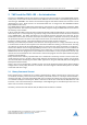
TMCM-3230 TMCL™ Firmware Manual • Firmware Version V1.07 | Document Revision V1.05 • 2017-OCT-10 L 88 / 103 R start stop left limit / end / stop switch right limit / end / stop switch : reference search speed (axis parameter 194) : reference switch speed (axis parameter 195) Figure 5: Reference search Mode 3 6.1.4 Mode 4 Reference search mode 4 searches the left end switch only, but from both sides so that the middle of the switch will be found and used as the zero point. This is shown in figure 6.
TMCM-3230 TMCL™ Firmware Manual • Firmware Version V1.07 | Document Revision V1.05 • 2017-OCT-10 89 / 103 Home L R start stop left limit / end / stop switch home switch : reference search speed (axis parameter 194) : reference switch speed (axis parameter 195) Figure 7: Reference search Mode 5 6.1.6 Mode 6 Reference search mode 6 searches the home switch in positive direction. The search direction will be reversed if the right limit switch is reached. This is shown in figure 8.
TMCM-3230 TMCL™ Firmware Manual • Firmware Version V1.07 | Document Revision V1.05 • 2017-OCT-10 L 90 / 103 R start stop home switch : reference search speed (axis parameter 194) : reference switch speed (axis parameter 195) Figure 9: Reference search Mode 7 6.1.8 Mode 8 Reference search mode 8 searches the home switch in positive direction, ignoring the limit switch inputs. It is recommende mainly for use with a circular axis. The exact middle of the switch will be found and used as the zero point.
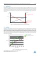
TMCM-3230 TMCL™ Firmware Manual • Firmware Version V1.07 | Document Revision V1.05 • 2017-OCT-10 6.2 91 / 103 stallGuard2 The module is equipped with motor driver chips that feature load measurement. This load measurement can be used for stall detection. stallGuard2 delivers a sensorless load measurement of the motor as well as a stall detection signal. The measured value changes linear with the load on the motor in a wide range of load, velocity and current settings.
TMCM-3230 TMCL™ Firmware Manual • Firmware Version V1.07 | Document Revision V1.05 • 2017-OCT-10 6.3 92 / 103 coolStep This section gives an overview of the coolStep related parameters. Please bear in mind that the figure only shows one example for a drive. There are parameters which concern the configuration of the current. Other parameters are there for velocity regulation and for time adjustment. Figure 11 shows all the adjustment points for coolStep.
TMCM-3230 TMCL™ Firmware Manual • Firmware Version V1.07 | Document Revision V1.05 • 2017-OCT-10 coolStep Adjustment Points and Thresholds Number Axis Parameter Description I6 Absolute maximum current The maximum value is 255. This value means 100% of the maximum current of the module. The current adjustment is within the range 0. . . 255 and can be adjusted in 32 steps (0. . . 255 divided by eight; e.g. step 0 = 0. . . 7, step 1 = 8. . . 15 and so on).
TMCM-3230 TMCL™ Firmware Manual • Firmware Version V1.07 | Document Revision V1.05 • 2017-OCT-10 6.4 94 / 103 Velocity and Acceleration Calculation When the unit mode (axis parameter #255) is set to 1 (which is also the default value), all velocity parameters on the TMCM-3230 are given in microsteps per second (also called pulse per second or pps). Acceleration and deceleration units are given in pps2 . When axis parameter #255 is set to 0 the internal units of the ramp generators are directly used.
TMCM-3230 TMCL™ Firmware Manual • Firmware Version V1.07 | Document Revision V1.05 • 2017-OCT-10 7 95 / 103 TMCL Programming Techniques and Structure 7.1 Initialization The first task in a TMCL program (like in other programs also) is to initialize all parameters where different values than the default values are necessary. For this purpose, SAP and SGP commands are used. 7.2 Main Loop Embedded systems normally use a main loop that runs infinitely.
TMCM-3230 TMCL™ Firmware Manual • Firmware Version V1.07 | Document Revision V1.05 • 2017-OCT-10 17 96 / 103 WAIT POS , Motor0 , 0 JA MainLoop Have a look at the file TMCLParam.tmc provided with the TMCL-IDE. It contains symbolic constants that define all important parameter numbers. Using constants for other values makes it easier to change them when they are used more than once in a program. You can change the definition of the constant and do not have to change all occurrences of it in your program. 7.
TMCM-3230 TMCL™ Firmware Manual • Firmware Version V1.07 | Document Revision V1.05 • 2017-OCT-10 7.5 97 / 103 Using Subroutines The CSUB and RSUB commands provide a mechanism for using subroutines. The CSUB command branches to the given label. When an RSUB command is executed the control goes back to the command that follows the CSUB command that called the subroutine. This mechanism can also be nested. From a subroutine called by a CSUB command other subroutines can be called.
TMCM-3230 TMCL™ Firmware Manual • Firmware Version V1.07 | Document Revision V1.05 • 2017-OCT-10 98 / 103 This example provides three very simple TMCL routines. They can be called from a host by issuing a run command with address 0 to call the first function, or a run command with address 1 to call the second function, or a run command with address 2 to call the third function.
TMCM-3230 TMCL™ Firmware Manual • Firmware Version V1.07 | Document Revision V1.05 • 2017-OCT-10 8 99 / 103 Figures Index 1 2 3 4 5 6 stallGuard2 Load Measurement as a Function of Load . . . . . . . . . . . . Energy Efficiency Example with coolStep Reference search Mode 1 . . . . . . . Reference search Mode 2 . . . . . . . Reference search Mode 3 . . . . . . . Reference search Mode 4 . . . . . . . 6 6 87 87 88 88 ©2017 TRINAMIC Motion Control GmbH & Co.
TMCM-3230 TMCL™ Firmware Manual • Firmware Version V1.07 | Document Revision V1.05 • 2017-OCT-10 9 100 / 103 Tables Index 1 2 3 4 5 6 7 8 9 10 11 12 13 TMCL Command Format . . . . . . . . TMCL Reply Format . . . . . . . . . . . TMCL Status Codes . . . . . . . . . . . Overview of all TMCL Commands . . . Motion Commands . . . . . . . . . . . Parameter Commands . . . . . . . . . Branch Commands . . . . . . . . . . . I/O Port Commands . . . . . . . . . . Calculation Commands . . . . . . . .
TMCM-3230 TMCL™ Firmware Manual • Firmware Version V1.07 | Document Revision V1.05 • 2017-OCT-10 10 101 / 103 Supplemental Directives 10.1 Producer Information 10.2 Copyright TRINAMIC owns the content of this user manual in its entirety, including but not limited to pictures, logos, trademarks, and resources. © Copyright 2017 TRINAMIC. All rights reserved. Electronically published by TRINAMIC, Germany.
TMCM-3230 TMCL™ Firmware Manual • Firmware Version V1.07 | Document Revision V1.05 • 2017-OCT-10 102 / 103 or of any other nature are made hereunder with respect to information/specification or the products to which information refers and no guarantee with respect to compliance to the intended use is given. In particular, this also applies to the stated possible applications or areas of applications of the product.
TMCM-3230 TMCL™ Firmware Manual • Firmware Version V1.07 | Document Revision V1.05 • 2017-OCT-10 11 11.1 103 / 103 Revision History Firmware Revision Version Date Author Description 1.04 2016-JUL-13 OK First release. 1.05 2016-NOV-02 OK Bugfix: TMCL program could be overwritten by user variables. 1.07 2017-JUN-08 OK Position reached event command fixed. USB OTG power disabled. Table 21: Firmware Revision 11.2 Document Revision Version Date Author Description 1.