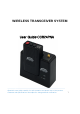
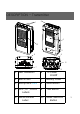
WIRELESS TRANSCEIVER SYSTEM User Guide :: CCR24PNA User Guide:CCR24PNA --------------------------------------------------------•Read this user guide carefully for safe operation and proper use of the product. •Features and specifications are subject to change without notification.
Safety Approval FCC ID: ROYCCR24PNAR ROYCCR24PNAT This device complies with Part 15 of the FCC Rules. Operation is subject to the following two conditions : (1) This device may not cause harmful interference, and (2) This device must accept any interference received, including interference that may cause undesired operation. CAUTION : Changes or modifications not expressly approved by the party responsible for compliance could void the user s authority to operate this device.
Safety Approval Industry Canada IC ID: 5479A-CCR24PNAR 5479A-CCR24PNAT Operation is subject to the following two conditions: (1) This device may not cause interference and (2) This device must accept any interference, including interference that may cause undesired operation of the device. The term “IC:” before the certification/registration number only signifies that registration was performed based on a Declaration of Conformity indicating that Industry Canada technical specifications were met.
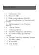
BOX CONTENTS • • • • • • • • • • • • • 1. Transmitter (TX) 2. Receiver (RX) 3. Plug-In Microphone (MONO) 4. Mounting Bracket for Receiver with screws 5. Rechargeable Li-Ion Polymer Battery 6. Leather Pouch 7. External antenna 8. Desktop charger for transmitter 9. AC Power supply for desktop charger 10. Charger Stand for Desktop Charger 11. RF Main Cable 12. In-car MIC 13.
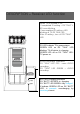
DESCRIPTION - Transmitter 3 1 4 2 5 6 9 8 7 10 1 LED Indication 6 TX Power On/Off 2 Built in MIC 7 Battery Cover 3 Microphone Jack 8 Mute Button 4 FCC , IC , cULus Labels 9 Talk Button 5 Serial Number Label 10 Mode Selection Button 3
DESCRIPTION - Receiver 1 2 4 6 3 7 5 1 Antenna connection 5 Serial Number Label 2 Talk On (Green LED) 6 Main Cable Connection 3 Battery Charger Status (Green + Red LED) 7 FCC , cULus , IC Labels 4 Charging PIN/Matching ID #2 Talk On LED When TX triggers the recording of the system , Green LED light on #3 Charging Status Red LED-In Charging 4 Green LED-Fully charged
DESCRIPTION – Receiver LED function When TX is docked in RX If completed ID setting – RX “TALK” L ED once blinking If uncompleted ID setting –LED blinking at TX,RX TALK LED After ID setting , turn off RX “TALK” LED When TX is docked in RX RX LED indicate TX’s power status. GREEN LED on RX “TALK” LED blinking- TX off status, in charging GREEN LED off on RX “TALK” LEDTX power on AUDIO recording indication RX “TALK” LED OFF- none AUDIO recording RX “TALK” LED GREEN – AUDIO recording.
DESCRIPTION – Control Reference Guide Transmitter (TX) with Receiver (RX) Top of Transmitter(TX) Internal Mic “REC”, “Mute” “Low Battery”, “Out of Indication Green Range”, LED “Mute” indication Red LED TALK Button Press for REC MODE Selection Button [TALK] Green LED ON/OFF: REC ON/OFF Green LED Blinking: ID Matching (Synch) ON [BATT] Red: In Charging Green: Fully charged Mute Button Lapel Mic Input Bottom of Transmitter(TX) Power ON/OFF Button 6
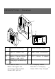
OPERATION - Install the mounting bracket by using the screws Slide RX Set onto the Bracket Connect the main cable to RX Set Connect external antenna to the RX Set. Assemble the battery pack into TX Set - How to change battery pack -Separate battery cover as shown next picture. - Separate battery pack with connector. - Assemble the new battery pack into TX set. -Assemble battery cover as initial. - Before using, battery cover should be assembled completely.
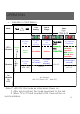
OPERATION • Indication of LED Button Mode LED+ Vibration Vibration TALK Green On LED OFF REC Low Battery Out of Range V(1 time only) V(1 time per second) V(2 times per 3seconds) Green Blink V(1 time only) LED OFF No Vibration No LED Red Blink Red On V (1 time per second) V (2 times per 3 seconds) Mute TALK (REC OFF): Green ON REC: Green Blink V(1 time per 5seconds TALK: Green ON & Red Fast Blink REC: Green Blink & Red Fast Blink V (1 time per 5 seconds) LED OFF LED OFF LED OFF No
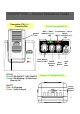
DESCRIPTION – Main Cable 1A In-Line fuse To Receiver # Important -These three ground wires have to be all connected together - Power ground wire from CCR24PNA, Trigger ground wire from CCR24PNA,and Ground wire of the Recorder GPIO. Connection with the system - Power DC12V (Red), Power GND (Black): Power Cables to engine battery. - Audio Out (RCA Connector) : Connects to “AUDIO IN” port in the back of recorder. - Trigger REC (Brown): Connect to GPIO cable.
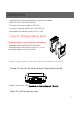
DESCRIPTION – Desktop Charger * Battery LED : In Charging – Red LED Fully Charged – Green LED (4V ~ 4.2V) (Note) Place TX on the charger at least 4.5sec for the initializing. Installation for Charger Stand Charger Stand TIP1 How to undock TX from RX and Home Charger To prevent units from being broken by the improper use, undock TX unit from RX unit as the drawing described on the right picture.
RECOMMENDATIONS - Prior to use, charge TX at least 3 hours - Disconnect the battery or switch the power OFF.
SPECIFICATION Power DC 12V for RX Frequency (MHz) 2.4GHz FHSS with 2,401.056 ~ 2,478.816MHz Number of Channel 91Channels Channel Space 864 KHz Speech Coder 32Kbps ADPCM with Parity Type of Modulation GFSK MODULATION / DEMODULATION Data Rate 576Kbps Time Division Duplex Receiver Sensitivity Min : -90 dBm Typ.: -92 dBm to -94 dBm @BER = 0.
SPECIFICATION SC14435 2G4HZ Frequency hopping The number of used frequencies (NUF) in the hopping algorithm is 95. In base and handset a Primary Hopping lndex Number (PHIN) exist. This number is incremented modulo NUF in the end of the normal downlink half-frame. It is broadcast in Q0 message instead of PSCN. To a simplex or established duplex bearer a Hopping Index Offset (HIO) is assigned, which is an analogue to the used RF carrier in a FDMA system. This value is broadcast in place of CN in Q0 message.
CAUTION • • • Li-Ion Battery Safety Precautions (sample document) 1. When Using the Battery Danger • (1) Misusing the battery may cause the battery to get hot, explode, or ignite and cause DANGER serious injury. Be sure to follow the safety rules listed below: . Do not place the battery in fire or heat the battery. . Do not install the battery backwards so that the polarity is reverse d. .
CAUTION • • • or appears abnormal in any other way. Contact your sales location or Panasonic if any of these problems are observed. (2) Do not place the batteries in microwave ovens, high-pressure c ontainers, or on induction cookware. (3) In the event that the battery leaks and the fluid gets into one’s e ye, do not rub the eye. Rinse well with water and immediately seek medical care. If left untreated the battery fluid could cause damage to the eye.
CAUTION • • 2. While Charging Caution • The temperature range over which the battery can be charged is 10 °C to 45°C. Charging the battery at temperatures outside of this ran ge may cause the battery to become hot or to break. Charging the battery outside of this temperature range may also harm the perfor mance of the battery or reduce the battery’s expectancy. • • 3. When Discharging the Battery Danger • Do not discharge the battery using any device except for the specif ied device.