
User's Manual


Page 32
E Series Data Radio – User Manual
© Copyright 2005 Trio DataCom Pty. Ltd.
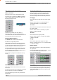
Bar Graph Indicators
The bar graph indicators on the front panel provide variable
information regarding the performance of the Base Station. To
enable / disable the bar graph display depress the Display ON /
OFF button. The display will turn off automatically after 5 minutes.
DC Supply:
Indicates the supply input voltage at the exciter module. Typically
13.8Vdc.
Indication: <10Vdc no LED’s on, 10-10.9Vdc LED’s RED, 11-
15.6Vdc All LED’s GREEN, >=15.7Vdc last LED RED.
Tx Power:
Indicates forward RF power output as measured at the TX antenna
port. Typically +37dBm.
Indication: <20dBm no LED’s on, 20-40.6dBm (11.5W) LED’s
GREEN, >=40.7dBm last LED RED.
Tx Drive:
Indicates exciter drive level. Typically +20dBm.
Indication: <10dBm no LED’s on, 10.0-25.9dBm LED’s GREEN,
>=26.0dBm last LED RED.
Rx Sig:
Indicates receive signal strength. Typically -85 to -65dBm.
Indication: <-120dBm no LED’s on, -120 to -110.1dBm LED’s RED,
>=-110dBm LED’s GREEN.
RxFreq. Offset:
Indicates offset of receiver AFC - useful in determining frequency
drift. Typically 0kHz.
Indication: Single GREEN LED to indicate current value, <-3.6kHz
or >+3.6kHz LED is RED. No signal, all LED’s OFF.
Note: 5 second peak hold circuitry.
Part E – Getting Started - EB450
Test Mode
The Bar Graph indicators have a Test Mode, which cycles all LED’s
for correct operation (before returning to their normal operation).
To activate this mode, simply depress the ON / OFF button while
applying power to the unit.
Hardware Error
A hardware error is indicated on the status LEDs by all
LEDs flashing RED at a rate of 1Hz. This indicates internal
communications to the exciter inside the basestation has been lost
and the base station needs to be returned to repair.
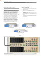
Received Signal Indicator
The “RX/SYNC” LED indicates the state of the receiver.
If the LED is off, no signal is being received.
A RED indication shows that an RF carrier is being received, but
no data stream can be decoded. This will briefly happen at the
very start of every valid received transmission or may indicate the
presence of interference, or another user on the channel.
A continuous GREEN indication shows that the modem is locked
and synchronised to the incoming signal, and has excellent Bit
Error Rate (BER). Any losses of synchronisation (BER errors) are
shown as a visible RED flicker of the LED.
Note: This might only be apparent on a PTMP slave when only
receiving.
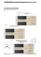
Data Flow “breakout” LEDs
There are also two LEDs to indicate data flow into and out of the
two user ports.
Input data to be transmitted is shown as a RED flash, and received
data to be output to the port is shown as a GREEN flash.
If data is alternately flowing in and out quickly, then the indicator
appears Orange.
LED Indicators & Test outputs
Radio is Powered
If all the LEDs are off, no power is reaching the radio modem.
Successful power-up is indicated by the “PWR” LED indicating a
continuous (healthy) GREEN state. Note that this LED is turned
RED when the transmitter is active.
LED Legend