
User's Manual


Page 34
E Series Data Radio – User Manual
© Copyright 2005 Trio DataCom Pty. Ltd.
Operational Description
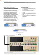
The Hot Standby Controller (HSC) unit is a 1RU rack mounted
module that interfaces to two physically separate base stations
(each 2RU rack mounted modules) via a number of RF and data
cables.
Both base stations are operating simultaneously and both units
are constantly receiving signals, however only data from one base
station, the “online” base station is directed to the user equipment.
The online base station is the only base station transmitting at any
time. The Hot Standby Controller has the following functions:
• Diplex the transmit and receive paths (Assuming internal
duplexer fitted), TX Only.
• Amplify and split the incoming signal two ways so both base
stations receive at once.
• Monitor status reports from both base stations to identify
faults and swap over the online base station if required.
• Switch the antenna via internal coaxial relay duplexer to the
online base station transmitter and inhibit the offline base
station from transmitting.
• Switch the User A and B data ports through to the online
base station.
An optocoupler based switch in the base station controller directs
data to and from ports A and B on the rear panel directly to ports A
and B on the on-line base station without any involvement from the
Hot Standby controller microcontrollers (apart from selecting the
on-line base). This provides protection of the system from failure of
the microcontroller.
As well as ports A and B, each base has a system port. The system
port of each base station is interfaced to the microcontroller on the
Hot Standby controller. This allows the microcontroller in charge
of selecting the base station to receive diagnostic messages from
each base station to decide their health.
The base station has it’s own system port on the rear panel and
this is interfaced to the Hot Standby Controller Module. The HSC
will route diagnostics at the rear panel system port to and from the
system ports of the base stations.
Warning
The base station front panel system port has priority over the
rear panel port, which is used for communication between the
base station and the Hot Standby Controller. This is to permit
service personnel to reconfigure the base station module without
disconnection from the Hot Standby Controller. It should be noted
however, that when the front panel port is accessed, a changeover
event will occur due to lost communications with the Hot Standby
Controller.
Mounting and Environmental
Considerations
The EH450 Hot Standby Base Station is housed as a 5RU 19” rack
mounted set, encompassing 2 x 2RU Base Station units and 1 x
1RU Hot Standby Controller unit. The mounting holes on the front
panels should be used to secure the units to the rack.
The unit should be mounted in a clean and dry location, protected
from water, excessive dust, corrosive fumes, extremes of
temperature and direct sunlight. Please allow sufficient passive or
active ventilation to allow the radio modem’s heatsink to operate
efficiently.
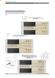
All permanent connections are made at the rear of the unit. This
includes: Power, Antenna, Communications Ports, Digital I/O
and System Port. The front panel has an additional System Port
connection point for easy access.
The Base Station front panel system ports must not be used while
in this configuration.
Part E – Getting Started - EH450