
User's Manual


Page 37
E Series Data Radio – User Manual
© Copyright 2005 Trio DataCom Pty. Ltd.
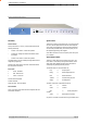
Front Panel Operation
Switches
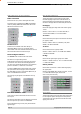
Select Switch
The 3 position switch (1 / Auto / 2) on the front panel provides the
following functionality:
• Position 1: base station 1 is forced into operation
• Position Auto: changeover hardware will select the online
base station
• Position 2: base station 2 is forced into operation
The select switch is also used to identify the target base station for
configuration programming.
Adjacent to the select switch are two LEDs: These LEDs indicate
the current active base station.
Select LEDs
• Green - Auto Mode
• Red - Remote Force
• Amber - Local Force
2 Green Firmware Download
2 Amber Test Mode
2 Red Fatal Error - refer User Manual
Reset Switch
This is a momentary close switch which when depressed will reset
all LED alarm indications.
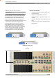
System Port
There are two system port connection points, one on the rear panel
and one on the front panel. Both have the same functionality and
can be used for local diagnostics, firmware front panel downloads
and hot standby controller testing. To access the system port use
the diagnostic/programming cable supplied.
Note: When connection is made to front panel system rear system
port is disabled.
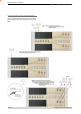
Alarm Status LEDs
There are 10 alarm LEDs on the front panel, five for base 1 and
five for base 2. These LEDs provide a general indication of base
station status. More detailed base station status information is
available by using the diagnostic utility software.
The indicated alarms for each base station are:
Freq. => Frequency Error
RxSig => Receive Signal (RF) Error
Data => Receive Data Error
TxPower => Transmit Power (RF) Error
Supply => DC Voltage Error
The status of each alarm is represented as follows:
OFF => Unknown
Green => No Error
Red => Current (active) Error
condition
Amber => Recovered Error condition
Any active or recovered error LEDs will turn to green after the reset
Part E – Getting Started - EH450