
User's Manual


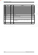

Table Of Contents
- Part A – Preface
- Warranty
- Important Notice
- FCC Compliance Notices
- Australian Compliance Notices
- Other Related Documentation and Products
- Revision History
- Part B – O Series Overview
- Definition of O Series Data Radio
- O Series Product Range
- O Series – Features and Benefits
- Standard Accessories
- Part C – Applications
- Application Detail
- Part D – Module Pinouts
- Part E – System Planning and Design
- Understanding RF Path Requirements
- Examples of Predictive Path Modelling
- Selecting Antennas
- Power Supply and Environmental Considerations
- Part F – Mounting and LED Indicators
- Mounting
- Antenna Port Cabling
- Product Labelling
- LED Indicators
- Part G – Specifications
- Appendix – FCC Approved Antennas

Page 9 © Copyright 2007 Trio DataCom Pty. Ltd.
O Series Data Radio – User Manual
Pin Name
In/Out
Comment Level
28 TxSync Output O Tx Sync output 3.3V TTL
29 PORT1-TxD I Input for transmit for Port 1 [Port B on K-Series] 3.3V TTL
30 PORT1-RxD O Output for received data for Port 1 [Port B on K-Series] 3.3V TTL
31 PORT1-RTS I Flow control of TxD for Port 1 [Port B on K-Series] 3.3V TTL
32 PORT1-CTS O Flow control of TxD for Port 1 [Port B on K-Series] 3.3V TTL
33 PORT1-DTR I Flow control of RxD for Primary Data Port [Port B on K-Series] 3.3V TTL
34 PORT1-DCD O Flow control of RxD for Port 1 [Port B on K-Series] 3.3V TTL
35 TWD IO I2C Data IO 3.3V TTL
36 TWCK O I2C Clock 3.3V TTL
37 SUPPLY_MONI-
TOR
I Used to monitor the 10-30V input supply. Requires external 15k/1k resistive
divider. (0-48V monitor range)
0-3V,
Hi-Z
38 SHUTDOWN_
OUT
O Used to shutdown the main switcher once the uP is in the correct state 3.3V TTL
39 NoSIG_LED O Masters: not activity
Remotes/Bridges: pulsed every 1500ms for 100ms when master not ac-
quired (Active Low)
3.3V TTL
40 NVRAM-WP O Connected to the write protect pin on the NVRAM on the K-Series (Active
High)
3.3V TTL