NWLTM Water Product User’s Manual NWL-TRN-001
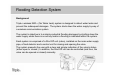
Flooding Detection System Background Triple+ wireless NWL™ (No Water Leak) system is designed to detect water leaks and prevent the subsequent damages. The system shuts down the water supply by way of a wireless communication system. The system's objective is to minimize potential flooding damages by shutting down the water supply when there is no activity and/or a flooding is indicated within the system.
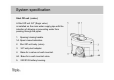
System specification Shut Off unit (valve ) A Shut Off unit 3/4" (Sagiv valve) is installed on the main water supply pipe with the intention of allowing or preventing water from passing through the pipes. 1. Opening/ closing handle. 1A. Open/ closed indication. 2. Shut Off unit body (valve). 3. 3/4" entry/exit adapter. 4. Base for a valve not wall mounted. 4A. Base for a wall mounted valve. 5.
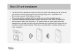
Shut Off unit installation • • • • The Shut Off unit should be located on the main water line leading into the structure. The system should not disconnect a fire extinguishing line or a sprinkler line. Ensure easy access to the battery housing.
Places where the detector should NOT be positioned • Within a metal cabinet • Where dirt or a foreign object may obstruct the valve's operation. • Where the temperature exceeds the range between 0 and 55 degrees centigrade. • Where there is an apprehension of being hit or damaged. • In an external place where exposed to rain and direct sunlight and/or to the elements, the unit should be installed in a watertight plastic casing.
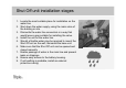
Shut Off unit installation stages 1. Locate the most suitable place for installation on the water line. 2. Shut down the water supply, using the main valve of the building or site. 3. Dismantle the water line connectors in a way that would leave a gap suitable for installing the valve. 4. Install the unit on the water line. 5. Should a flexible water pipe be required to mount the Shut Off unit on the wall, dismantle the base unit. 6. Make sure that the Shut Off unit can be opened and closed manually. 7.
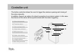
Controller unit The button controller allows the user to trigger the wireless opening and closing of the valve manually. In addition, there is an option of a direct connection to an alarm system. In this case the closure of the valve will be synchronized with the alarm triggering. 1A. Valve closing button. 5 1B. Technician button. 1C. Valve opening button 3A. Water battery indicator 5. 5VDC power input 4 3C 3D 3A 1C 1A 3B. Water valve indicator. 3C. Communications light. 3D. Voltage indicator 4.
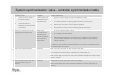
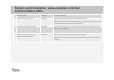
System synchronization: valve - controller synchronization table OPERATION 1 I. II. Shift the valve handle to the open position. Location Control indication A water valve that is installed on the main water line I. A green indicator lights up within the battery housing. II. The valve performs an opening action and then a closing one. III. Wait for the conclusion of the engine's operation. IV. Ensure that the valve can be manually opened and closed. I. The four indicators flash 3 times. II.
System synchronization: valve - controller synchronization table 1 OPERATION Location Control indication I. A water valve that is installed on the main water line I. A green indicator lights up within the battery housing. II. The valve performs an opening action and then a closing one. III. Wait for the conclusion of the engine's operation. IV. Ensure that the valve can be manually opened and closed. II. 2 Shift the valve handle to the open position.
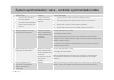
System synchronization: valve-repeater-controller synchronization table 5 OPERATION Location Control indication Press the technician button Repeater After some thirty seconds, all four indicators will flash. Make sure that the green indicator lights are continuously on (voltage, valve communication and controller communication.) 6 Ensure valve indication transfer CONTROL After another thirty seconds, the open valve indicator indicates the valve's state (open or closed.
System synchronization: flood detector - controller synchronization table 1 OPERATION Location Control indication Press the valve "Open" and "Close" buttons simultaneously. CONTROL Red indicator - valve battery is continuously on. Green indicator - voltage flashing. 2 Open the battery cover and insert two AA batteries into the flood detector. Position the flood detector where measurements indicate qualitative and continuous transmission from the valve and the controller. I.
Synchronization reset (Hard reset) Pressing five consecutive times will lead to disconnection between the system's components. Reset of the valve is possible by pressing five consecutive times the technician button in the controller, while pressing the "Open" and "Close" buttons simultaneously and pressing five consecutive times the technician button in the controller.
Additional clarifications regarding the installation of the flood detector 1. A technician must visit the installation site before performing a hard reset to identify the nature of the communication with a tester/ installation instructions/ common sense. 2. The system controller will not work with batteries but by way of electricity transformer. 3. The controller should not be connected to an alarm system. 4.
Replacement of the disconnection unit (valve) 1. Take the batteries out of the faulty unit that is being replaced. 2. Reset the controller (press HARD RESET five times.) 3. Dismantle the unit from the water line and perform all the stages specified in the disconnection unit installation instruction. 4. Synchronize the controller - valve system. The detectors retain synchronization with the controller.
Controller replacement 1. Disconnect the transformer from the faulty control box to be replaced. 2. Pull the control box out of its place. 3. Perform all the control unit installation stages. 4. Perform a full synchronization process (including extraction, pause and replacement of the batteries in the valve) and full synchronization with all the flood detectors.
Replacement of a battery in the Shut Off unit (valve) 1. Extract two CR123 batteries out of the unit and replace with new ones. 2. Verify system synchronization by closing and opening the valve using the controller buttons.
System failure indication table 1 2 OPERATION Location Control indication No communication Communications light flashing or off. 1. Check the battery voltage in the flood detector. 2. Consider narrowing the transmission distance. 3. Considering adding a relay (repeater.) 1. Make sure there are no obstructions in the valve's opening and closing path. 2. Open and close the valve using the controller buttons 3. Extract and replace the batteries in the valve and check the fault status. 4.
FCC Statement NOTE: This equipment has been tested and found to comply with the limits for a Class B digital device, pursuant to part 15 of the FCC Rules. These limits are designed to provide reasonable protection against harmful interference in a residential installation. This equipment generates, uses and can radiate radio frequency energy and, if not installed and used in accordance with the instructions, may cause harmful interference to radio communications.
FCC Disclaimer Manufacturer: Triple Plus Ltd. This device complies with Part 15 of the FCC Rules. Operation is subject to the following two conditions: (1) This device may not cause harmful interference, and (2) this device must accept any interference received, including interference that may cause undesired operation. Le présent appareil est conforme aux CNR d'Industrie Canada applicables aux appareils radio exempts de licence.