
User's Manual

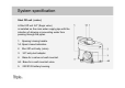
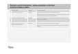

System synchronization: valve - controller synchronization table
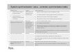
OPERATION Location Control indication
1
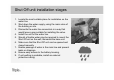
I. Shift the valve handle to
the open position.
II. Insert two CR123
batteries into the Shut Off
unit (valve.)
A water valve that
is installed on the
main water line
I. A green indicator lights up within the battery housing.
II. The valve performs an opening action and then a closing one.
III. Wait for the conclusion of the engine's operation.
IV. Ensure that the valve can be manually opened and closed.
2
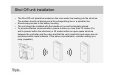
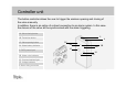
Hook the controller to the main
supply with the transformer.
Position the
controller where
measurements
indicate qualitative
and continuous
transmission.
I. The four indicators flash 3 times.
II. The voltage indicator flashes.
III. Wait for approximately two minutes by the controller to ensure that the
communication indicator is lit continuously (in addition to the flashing
voltage indicator.)
In case the communication indicator flashes or is turned off, a repeater should
be installed within the system.
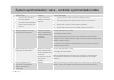
3
Press the technician button Controller After some thirty seconds, all four indicators will flash.
The voltage and communication indicators are continuously on.
After another thirty seconds, the open valve indicator indicates the valve's state
(open or closed.)
4
Synchronization test: open and
close the valve using the
buttons
Controller Check that the valve opens and closes accordingly.
Make sure that the open valve indicator indicates the valve's state (open or
closed.)