
Manual
Page 22
5.0 OPERATION
5.1 Measuring AC and DC Voltage
5.1.1 Refer to Section 3.0, Preparation For Use, and Section 4.0,
General Operation, before attempting any measurements.
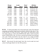
5.1.2 Select the desired AC or DC voltage range by rotating the
Range Switch to the desired range. If measuring AC voltage with a
Test Set with Cab Filters (SIGNAL SEL. switch will be marked CAB
FILTER), set the Signal Select Switch to the AP +/- (ALL PASS /
AUTO POLARITY) position to measure all AC voltage present. Dam-
age can result if high voltages are present at other than the selected
frequency. If only the cab signals are of interest, then set the Signal
Select Switch to the appropriate frequency. The Test Set will mea-
sure only that signal. A Test Set without Cab Filters will measure all
AC voltage present, regardless of the setting of the Signal Select
Switch. In DC Volts, the position of the Signal Select Switch has no
effect but should be left in the AP +/- or +/- position to avoid mis-
interpretation.
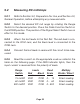
5.1.3 Attach the test leads to the Test Set. The red lead is con-
nected to the VOM Jack, and the black lead is connected to the
COM Jack.
5.1.4 Connect the test leads across the circuit to be measured.
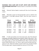
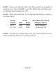
5.1.5 Read the voltage on the appropriate scale as noted in the
table on the following page. If the NEG Indicator lights, then the
input voltage is reversed from the polarity of leads.