
Manual

Page 27
WARNING: THE 6 AMP AND 30 AMP JACKS ARE UNFUSED.
USE EXTREME CAUTION! The black lead is connected to the COM
Jack.
5.3.4 Connect the test leads in series with the circuit to be mea-
sured.
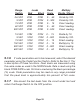
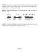
5.3.5 Read the current on the appropriate scale as noted in the
table below. If the NEG Indicator lights, then the input current is
negative.
Range Leads Read Multiply
Switch Red Black Scale Divide / Direct
DC Amps 1.5 A COM 0 - 15 Divide by 10.
DC Amps 6 A COM 0 - 60 Divide by 10.
DC Amps 30 A COM 0 - 300 Divide by 10.
AC Amps 1.5 A COM 0 - 15 Divide by 10.
AC Amps 6 A COM 0 - 60 Divide by 10.
AC Amps 30 A COM 0 - 300 Divide by 10.
5.3.6 If code parameters are to be measured, select the desired
parameter using the Code Function Switch. Refer to Section 2.1 for
a description of these functions. Peak levels are measured using
the same scales as used in the NORM mode. Rate is read using the
black CODE RATE scale. On Time is read using the black percent-
age (%) scale. Code parameters may be read on any range provided
that the peak level is approximately ten percent of full scale.