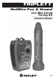
TRIPLETT HotWire Fox & Hound Live Wire Circuit Tracing Kit Instruction Manual 84-877 7-10
Table of Contents Features .................................................................. 1 Introduction ............................................................ 2 Warnings and Cautions ........................................... 3 Specifications for HotWire Fox ................................4 Specifications for HotWire Hound ...........................5 General Characteristics ........................................... 6 Control Location for HotWire Hound .......................
1: Overall Features * Trace Live 120VAC and 220VAC Power Lines * Locates Wires Through Drywall, Plaster, Wood, Cement, etc.
2: Introduction The Triplett HotWire is a wire tracer for 120VAC and 220VAC circuits. It consists of the HotWire Fox Transmitter and the HotWire Hound Receiver. The HotWire Fox applies a Radio Frequency (RF) tracing signal to the wire to be traced, and this RF signal propagates down the wire radiating the signal along the length of the wire. The HotWire Hound senses the location and strength of this RF signal, and in doing so, identifies the path of the wire to the user.
3: Warnings and Cautions * The HotWire is designed for use on 120VAC and 220VAC circuits. It is intended to be used on fused circuits that are not considered ‘High Energy’. This generally means that the circuits are appropriately fused to prevent explosive ‘follow on’ currents that can develop in response to an accidental arc. This usually means that the circuit is fused at 40A or less. * Never connect the HotWire to circuits exceeding 250VAC or 250VDC.
4: Specifications for HotWire Fox * Operating Frequency (RF): 400KHz to 500KHz * Operating Frequency (AF): 800Hz to 2400Hz * Output Voltage (RF): adjustable from approx.
5: Specifications for HotWire Hound * Operating Frequency (RF): 400KHz to 500KHz * Signal Indicators: Speaker outputs Tracer Signal and LED indicates signal strength * Earphone Jack: Accepts 1/8” mono or stereo earphone plug, 8 Ohms to 50 Ohms. Automatically mutes speaker. * Headlights: 2 High Brightness White LEDs * Speaker: Rugged 1.
6: General Characteristics There are many different types of wire tracers using different technologies to trace wires. While a single technology can be used to trace wires in many different scenarios, there is often a specific technology that works best for a specific scenario. While this instruction manual provides information on how to use the Triplett HotWire to perform various wire tracing tasks, the user should be aware that in some cases, other testing devices may work better than the HotWire.
The HotWire can be used to identify, for example, the end of a specific Cable TV wire among a group of Cable TV wires. However , if the wires are bundled together, crosstalk between the wires can make identifying a specific wire problematic. The Triplett WireMaster Coax or the Triplett WireMaster Mapper are better suited to this task, allowing up to 8 wires to be easily identified. The HotWire can be used to identify LAN cables…. and again crosstalk is a problem if the cables are bundled together.
Throughout this instruction manual, the user will be reminded of instances in which a ‘false trace’ can occur. After the user has some experience with using the HotWire, and sees firsthand how it behaves in various test scenarios, he will become more proficient at using the product, and recognize cases in which the HotWire will or will not produce reliable results.
The HotWire Hound senses RF current flowing in a conductor or the Electromagnetic waves in free space. In our application, we are interested in sensing the RF current in a conductor. In order for current to flow, there must be a complete ‘circuit’. When it comes to RF, the ‘circuit’ is not obvious, as it is with regular 60Hz AC household power. With AC, its easy to see how the power source, a light switch, and a light bulb are connected together to form a circuit.
7: HotWire Hound Control Locations A: ANTENNA B: LED HEADLITES C: SIGNAL STRENGTH INDICATOR D: POWER BUTTON E: VOLUME / SENSITIVITY CONTROL F: EARPHONE JACK G: BATTERY CONNECTOR H: BATTERY STRAP I: BATTERY COVER J: 9V BATTERY K: SPEAKER A) Antenna This area contains the RF sensing antenna. When using the HotWire Hound, this area is positioned for the strongest signal pickup, or for finding the “null” (more on this later). B) LED Headlights Two white LED headlights help illuminate the immediate area.
C) Signal Strength Indicator The Signal Strength LED is used to indicate the presence of a signal when it may be difficult to hear the signal coming from the speaker (because of high ambient noise levels). It will glow brighter as the received signal strength increases. The brightness will be seen to pulsate with the characteristics of the received signal. Helpful Hint The Signal Strength LED responds to any received signal. Any sound normally heard in the speaker will cause the LED to light.
G) Battery Connector Observing proper polarity, attach to 9V alkaline battery H) Battery Strap Slip over battery before installing in Hound. Position tab so it can be grabbed with fingers. This allows battery to be removed easily when it needs to be replaced. I) Battery Cover Removed and replaced easily using snap tab.
8: HotWire Fox Control Locations 1) Function Switch 2) Unlock Button 3) Battery Test / Cadence LED (green) 4) Voltage Present LED (red) 5) Pulse / Warble Button 6) TrueTrace On/Off Button 7) RF Level Control 8) TEST LEADS (PIGTAILS) 8) TEST LEADS (PIGTAILS) 9) MAGNETS 10) SCREWS (4 PLACES) 11) BATTERY CONNECTOR 12) 9V BATTERY 13) BATTERY COVER Page 14
Test Leads 1) 24” Test Leads 2) 60” Test Leads 3) Pointed Test Probe 4) Flat Test Probe 5) Alligator Clips HotWire Fox Control Description 1) Function Switch The Function Switch has 3 settings…… OFF / VOLTAGE TEST, TRACE / BATTERY TEST, and CONTINUITY BEEPER. a) In the OFF / VOLTAGE TEST setting, the HotWire Fox is turned off (not using any battery power) and is configured to test for AC or DC voltage on its Test Leads.
4) VOLTAGE PRESENT LED (red) This LED flashes when AC or DC voltage is present (see Specifications for details). In the OFF / VOLTAGE TEST and CONTINUITY modes, the flashing is accompanied by the beeper sounding. In the TRACER TONE mode, the Voltage Present LED will flash to indicate a voltage, but the beeper will not sound. 5) PULSE / WARBLE Button This button allows the user to select the ‘tone’ of the Tracer Signal. When PULSE is selected (button ‘in’), the Tracer Signal is a tone that pulses on and off.
9: Getting Started Installing / Replacing Battery Refer to the HotWire Fox and Hound Control Locations drawing. To install or replace the 9 volt battery in the HotWire Hound, remove the Battery Cover (I) by pressing the release tab towards the nose end of the case. Remove the Battery Connector (G) and the Battery Strap (H). Snap the Connector to a 9 volt battery (J) and slide the Strap over the battery. Position the Strap so that the finger tab is on the side of the battery.
Basic Operational Test Hold the HotWire Hound and press its POWER button. The white LED headlights should come on. If they don’t come on, replace the battery. Rotate the VOLUME / SENSITIVITY thumbwheel to its mid position and hold the nose of the Hound within a few inches of the Fox. The Fox’s tracing signal should be heard coming from the Hound’s speaker. Depending on the setting of the Fox, the signal may sound like a Warble or a Pulse.
The different lengths of Test Lead wire are provided not only for convenience in testing, but in some tests, the length of the leads has an effect on the traceability of the wire or circuit. This will be explained in more detail later. OFF / VOLTAGE TEST Function The HotWire Fox has a built-in Voltage Detector. It is intended to warn the user that voltage is present, and the proper precautions should be taken.
TRACER TONE Test Function Several different methods can be and should be employed to trace wires. Set the Function switch to the TRACER TONE position. The BATTERY TEST / CADENCE LED must flash. If it does not flash, replace the battery. Select the PULSE or WARBLE mode as desired. If the Pilot Tone is activated, you should be able to faintly hear the sound produced by the PULSE and WARBLE settings. If connecting to a live circuit, set the TrueTrace to OFF.
The Null Method The concept of the “null” is illustrated in the following drawing. When the HotWire Hound is passed perpendicularly over the wire with the HotWire Fox’s tracer signal, a strong signal will be picked up on either side of the target wire, and a ‘null’ (dead spot) will appear right over the wire. The null locates the wire within a few inches.
HotWire Fox connected to wall outlet Tracing wire in wall Identifying breaker by locating the “null”.
Helpful Hints It is usually best to start with the RF Level control all the way up on the HotWire Fox, adjusting the Sensitivity on the HotWire Hound so the tracer signal produces a comfortable loudness. If it is found that the Sensitivity of the HotWire Hound is turned almost all the way down, it may be hard to detect the peak or null of the target wire. In this case, reduce the RF Level setting on the HotWire Fox, and increase the Sensitivity setting on the HotWire Hound.
HotWire Fox connected to boundary wires HotWire Hound locates boundary wire using null method. Improving Null with Earth Ground When tracing a wire and the actual earth ground is available, it may be possible to improve the null effect and create a stronger tracer signal for the HotWire Hound to pick up. It’s important that ‘actual’ earth is used…. not a wire leading to the earth. An ‘actual’ earth is the soil itself, or concrete laid on the soil (like a garage floor or a factory floor).
HotWire Fox on ‘Earth’ Connect the red pigtail to either the 2’ or 5’ red test lead (use the shortest one you can), and connect the other end of the test lead to the wire to be traced. In the following photo, the target wire is connected to a wall outlet.
CAUTION: If the wall outlet is ‘live’, the black test lead will be live also. Use appropriate caution. Failure to do so could result in user injury. When using ‘single wire’ connection, the HotWire Fox will not indicate if the target wire is ‘live’. If you do not know if the target wire is ‘live’, use appropriate caution. Failure to do so could result in user injury.
The Peak Method The concept of the ‘peak’ method is illustrated in the following drawing. When the HotWire Hound is passed perpendicularly over the wire with the HotWire Fox’s tracer signal, a strong signal will be picked up as the Hound passes over the target wire. The signal will be strongest directly over the wire. Peak signal pick up usually happens when short wires are being traced, and the wires have no predominant RF path to earth ground.
occur that the tracer tone on the adjacent wires can be almost as large as the original tone on the target wires. This can make it difficult to identify the target wires with the HotWire Hound. To aid in identifying the target wires, the HotWire Fox uses TrueTrace.... a test technique which greatly improves the accuracy of the trace.
Wires usually do not radiate RF signals in a circular pattern around the wire. There is often a ‘lobed’ pattern, with the size and the shape of the lobes determined by various factors, including the construction of the wire, the placement of the wire in relationship to other wires or conductive surfaces, and the strength of the signal impressed on the wire by the HotWire Fox. Using the Single Wire Method or the Double Wire Method significantly affects the pattern and strength.
Noise Pickup: The HotWire Hound is tuned to the frequency of the HotWire Fox. RF noise is also found in this same frequency range. Noise comes from Light Dimmers, Motor speed controls, Power Paks (Wall Warts), Computers, etc. The HotWire Hound may also pick up radio or TV stations. Because electrical wiring often acts like an antenna, the HotWire Hound may pick up radio or TV stations as the Hound is brought close to these electrical wires.
12: Included Items The following items are included with the HotWire Fox and Hound HotWire Fox ………………………………….… Part Number 3388-FOX HotWire Hound …………………………...............Part Number 3388-HOUND Carrying Case …………………………………… Part Number 10-4300 Instruction Manual ……………………………… Part Number 84-877 Two 2’ Test Leads (1 red, 1 black) ………………..Part Number 79-805 Two 5’ Test Leads (1 red, 1 black) ………………..
Triplett Product Return Instructions In the unlikely event that you must return your Triplett equipment for repair, the following steps must be taken. 1) Call 1-800-TRIPLETT to obtain a Return Material Authorization (RMA) number from Customer Service. 2) Enclose a copy of the original sales receipt showing date of purchase. 3) Clearly print the RMA number on the outside of the shipping container. 4) Return to: Triplett / Jewell Instruments 850 Perimeter Road Manchester, NH 03103 ATTN: Repair Dept.
14: Triplett One Year Limited Warranty Triplett warrants instruments and test equipment manufactured by it to be free from defective material or workmanship and agrees to repair or replace such products which, under normal use and service, disclose the defect to be the fault of our manufacturing, with no charge within one year of the date of original purchase for parts and labor. If we are unable to repair or replace the product, we will make a refund of the purchase price.
T TRIPLETT Test Equipment & Tools 850 Perimeter Road, Manchester, NH 03103 PHONE: 800-TRIPLETT FAX: 603-622-2960 www.triplett.