CamView IP Pro Series Testers TM 8071 & 8073 USER MANUAL Rev.
Thank you for purchasing the Triplett CamView™ Pro/Pro-C/Pro+/Pro-D. Please read the manual carefully before using the product. To assure safe use of this product, please read the section on Safety carefully, and observe any Cautions or Warnings posted there and throughout this manual. Please keep this manual for future reference. SAFETY INFORMATION • Comply with all local electrical safety and electromagnetic compatibility rules and regulations when using this device.
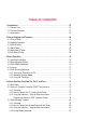
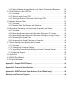
TABLE OF CONTENTS 1. Introduction . . . . . . . . . . . . . . . . . . . . . . . . . . . . . . . . . . . . . . . . . . . . . . . . . . . . . . 01 1.1 General Use . . . . . . . . . . . . . . . . . . . . . . . . . . . . . . . . . . . . . . . . . . . . . . . . . . . . 01 1.2 Function Summary . . . . . . . . . . . . . . . . . . . . . . . . . . . . . . . . . . . . . . . . . . . . . . . 01 1.3 Accessories . . . . . . . . . . . . . . . . . . . . . . . . . . . . . . . . . . . . . . . . . . . . . . . . . . . . 03 2.
.3.5 Testing Remote Analog Monitors and Optical Transmitters/Receivers . . . . . 24 4.4 RJ45 Ethernet Cable TDR Test. . . . . . . . . . . . . . . . . . . . . . . . . . . . . . . . . . . . . . 25 4.4.1 Overview . . . . . . . . . . . . . . . . . . . . . . . . . . . . . . . . . . . . . . . . . . . . . . . . . . . 25 4.4.2 Testing Length Using TDR . . . . . . . . . . . . . . . . . . . . . . . . . . . . . . . . . . . . . . 25 4.4.3 Testing for Breaks in Ethernet Cable Using TDR . . . . . . . . . . . . . . . .
CamView IP Pro Series Combined User Manual 1 1. INTRODUCTION 1.1 General Use The CamView IP Pro, Pro-C, Pro+, and Pro-D are designed to facilitate the installation and maintenance of surveillance video equipment. They can be used with Standard Definition analog NTSC/ PAL camera systems and High Definition ONVIF conformant IP (Ethernet) camera systems.
2 CamView IP Pro Series Combined User Manual You can adjust the camera’s settings, and record still images or video from the selected camera. You can also check the audio signal from the camera if it is equipped with a microphone. If the camera is directly connected, the Tester will provide POE voltage to power the camera. 1.2.2 Standard Definition Analog Camera Test The Tester can display the analog video signal input from an attached analog camera or video source with NTSC or PAL format video output.
CamView IP Pro Series Combined User Manual 3 1.2.7 Network Test The Tester may be used to perform several Ethernet network test functions, including: Network Sniff: Monitors and displays Ethernet MAC IDs and IP addresses broadcast on the network Subnet List: Monitors and displays Ethernet MAC IDs and IP addresses broadcast on the selected subnet according to IP and mask settings Ping Test: Performs the standard ping messaging response test on the specified destination IP address 1.2.
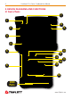
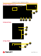
4 CamView IP Pro Series Combined User Manual 2. DEVICE DIAGRAMS AND FUNCTIONS 2.1 Front of Tester 7 1 8 2 9 3 4 5 12 15 6 11 14 10 13 16 DMM Ports www.Triplett.
CamView IP Pro Series Combined User Manual 5 1 Power Indicator — Lights up when powered on. 2 Title Bar — Displays current function mode and system time. 3 Display Area — Displays various user interface menus. 4 On-Screen Instructions — Displays what your options are in the current screen and how to apply them. 5 Bumpers — Rubber protectors to improve handling and protect the tester. 6 QWERTY Keyboard — Flip open this area to access the QWERTY keyboard.
6 CamView IP Pro Series Combined User Manual 2.2 Front of Tester (Keyboard) 21 17 18 19 22 20 2.3 Back of Tester 23 24 25 2.4 Top of Tester 27 26 28 www.Triplett.
CamView IP Pro Series Combined User Manual 7 17 TAB Key — Press to switch between input fields on the screen (e.g.
8 CamView IP Pro Series Combined User Manual 2.5 Right Side of Tester 29 30 31 32 33 34 2.6 Left Side of Tester 35 36 www.Triplett.
CamView IP Pro Series Combined User Manual 29 9 Power Button • Press and hold for 2 seconds to turn the tester on / off • Press twice quickly to turn the Flashlight on / off (Flashlight feature may be used while the tester is on) 30 Audio Input Jack — 3.
10 CamView IP Pro Series Combined User Manual 3. BASIC OPERATION 3.1 Installing the Battery The CamView IP series of testers use a rechargeable lithium-ion polymer battery. To ensure safety when transporting, always disconnect the battery from the tester. The device may leave the factory with one of the following two battery placements: • The battery is placed inside tester and insulated from the contacts with a thin, plastic sheet.
CamView IP Pro Series Combined User Manual 11 • The battery can also be charged using a POE switch or other POE power sources that meet the 802.3af / 802.3at standard. However, we strongly recommend using the original POE injector provided with your Tester. DO NOT USE A NON-STANDARD POE POWER SUPPLY TO CHARGE THE BATTERY—THIS CAN DAMAGE THE TESTER. 3.4 Lanyard Users can choose to install the lanyard.
12 CamView IP Pro Series Combined User Manual 4. HOW TO USE YOUR CAMVIEW IP PRO, PRO-C, OR PRO+ 4.1 Main Menu When the CamView IP Pro-C/Pro+/Pro-D first boots up, you will see the following Main Screen. (NOTE—CamView IP Pro Testers will show fewer options.) You can navigate this screen using the Up or Down Arrow Keys. Once you have highlighted the function you want to use, press the Right Arrow Key to go to the Interface Screen for that feature. 4.2 Testing IP Cameras using the ONVIF Test Interface 4.2.
CamView IP Pro Series Combined User Manual 13 OPTION 2 For non-POE IP cameras, the camera can either be powered using its own 12V power adapter or using the Tester’s 12V/2A power output. When using the Tester’s 12V/2A output, please use the 12V power cable supplied to connect the Tester’s 12V Output Port to the camera’s 12V power port. You can then connect the ethernet cable from the IP camera to the Tester’s Network Port 2.
14 CamView IP Pro Series Combined User Manual 4.2.3 Using the Interface Once you have connected the IP Camera to the Tester using one of the options listed in the previous section, follow these steps to perform IP Camera testing: STEP 1: Power Up the Tester Press the Power Button on the side of your Tester to turn it on if it is not already powered on. STEP 2: Select ONVIF Test On the Main Menu, highlight “ONVIF Test” (press the MODE button to enter the Main Menu if you are not already on it).
CamView IP Pro Series Combined User Manual 15 IP address to include “.../onvif/device_service” at the end of the original 10.1.1.100 address. The final result will look like this: http://10.1.1.100/onvif/device_service. Press Iris+ to accept the settings and return to the Discover screen.
16 CamView IP Pro Series Combined User Manual 41 42 43 44 37 45 38 46 39 40 37 Network Port 1 Status Information — Also referred to as the Blue Bar, all of the information for the camera connected to Port 1 (blue RJ45 port on the side of the Tester) will show in this row. 38 Network Port 2 Status Information — Also referred to as the Green Bar, all of the information from the network connected to Port 2 (green RJ45 port on the side of the Tester) will show in this row.
CamView IP Pro Series Combined User Manual 17 41 Link Speed of Corresponding Port — The Link Speed displays above the bar icon. shows for each Port. The link speed can also be observed via the icon itself. • If the bar icon is gray, there is no network connection. It will also say “Link Down” as shown in the sample image. • If the bar icon is white, the tester is sensing and will display the link speed (10M/100M/1000M) and whether the connection is Full or Half Duplex.
18 CamView IP Pro Series Combined User Manual CAMERA SETTINGS: While you are in the Discover screen, you can press the SET Key to enter the Camera’s Settings Screen. The left side of the display shows the Setting’s Class, and the right side shows the details of the camera’s setting within that class. The classes and details are explained in the table at the bottom of this page. Use Zoom +/- to move up or down to select the Class. To select right side items, use the Up and Down Arrow Keys.
CamView IP Pro Series Combined User Manual 19 You may also export a report about this camera by selecting the SCR Key. You can retrieve the report, along with any screenshots or recordings, by plugging the mini USB cable into the tester and then attaching it to your computer. Your computer will view the Tester as an external drive. See Appendix 1 for a sample report. STEP 6: ONVIF Video Testing While on the Discover screen, press the Right Arrow Key to move to the “3.
20 CamView IP Pro Series Combined User Manual 4.3 Testing Analog Cameras 4.3.1 Overview You can test standard Analog (NTSC/PAL) cameras with the Pro model, NTSC/PAL & HD-CVI with the Pro-C model, or you can test NTSC/PAL, AHD & HD-TVI cameras if you have the Pro+ model. 4.3.2 How to Connect the Analog Camera to the Tester Analog cameras are connected using the BNC In connector on the top of the Tester.
CamView IP Pro Series Combined User Manual 21 4.3.3 Using the Analog Camera Test Interface Once you have connected the Analog Camera to the Tester and set up the camera’s power supply, follow these steps to perform Analog Camera testing: STEP 1: Power Up the Tester Press the Power Button on the side of your CamView IP Pro, Pro-C, or Pro+ Tester to turn it on if it is not already powered on. STEP 2: Select Analog Camera Test On the Main Menu, highlight “Analog Camera Test” using the Down Arrow Key.
22 CamView IP Pro Series Combined User Manual To access and change the Tester’s settings to match the camera’s settings, press SET and then use the Arrow Keys to navigate the screen. (See image above.) When adjusting the parameters, press Iris- to restore previous values if you don’t want to save the setting. Once you have updated all of the settings, press SET again to save your changes. The changes will be applied immediately. Protocol Select RS485 PTZ protocol. The tester supports many PTZ protocols.
CamView IP Pro Series Combined User Manual 23 4.3.4 Analog Video Generator On the Main Menu, highlight “Analog Video Generator” (press the MODE button to enter the Main Menu if you are not already on it; press the Up or Down Arrow Keys to highlight it). Once the “Analog Video Generator” option is highlighted, press the Right Arrow Key to select the test. Live video will show in the right side of the screen if you have the Analog Camera hooked up to the BNC In jack on the Tester.
24 CamView IP Pro Series Combined User Manual 4.3.5 Testing Remote Analog Monitors and Optical Transmitters/Receivers You can transmit generated video to the remote monitor or DVR using the BNC Out jack (see image below). This will allow you to test the cable and monitor by comparing the image quality on the Tester to the image quality on the monitor.
CamView IP Pro Series Combined User Manual 25 4.4 Ethernet Cable TDR Test 4.4.1 Overview This feature is only available on the Pro-C, Pro+, and Pro-D models. It is primarily used to test the approximate cable length of an RJ45 cable by using a Time Domain Reflectometry (TDR) analysis method. However, you can also use this feature to test for breaks, Skew, and Attenuation. The accuracy is to within one meter.
26 CamView IP Pro Series Combined User Manual 50 51 52 53 47 48 49 47 Network Port 1 Icon 48 Tape Measure — Flashes just under the Network Port icon when a cable is being tested. 49 Network Port 2 icon 50 Cable Pairs — Both by number and color pattern. 51 Cable Pair Status — Test results for each pair are displayed here. • A solid horizontal line indicates pass-through (good cable; no breaks) • An X indicates the cable is not passing through.
CamView IP Pro Series Combined User Manual 27 STEP 3: Access the TDR Test Screen On the Main Menu, highlight “RJ45 Cable TDR Test” (press the MODE button to enter the Main Menu if you are not already on it; press the Up or Down Arrow Keys to highlight it). Once the “RJ45 Cable TDR Test” option is highlighted, press the Right Arrow Key to select the test. (See page 26 for a complete description of each feature on this screen.
28 CamView IP Pro Series Combined User Manual cable. The second example below shows the results from a cable with an open on the green pairs and the length to that open from each end of the cable. NOTE — Do not use the Repeat Test feature when performing this test as the test results will be compromised. www.Triplett.
CamView IP Pro Series Combined User Manual 29 4.5 Network Analysis Tools 4.5.1 Overview Network analysis is a combination of several network tools, including Ethernet Sniff, Subnet List, and Ping test. 4.5.2 Network Tools Test Screen and Operation On the Main Menu, highlight “Network Tools” (press the MODE button to enter the Main Menu if you are not already on it; press the Up or Down Arrow Keys to highlight it).
30 CamView IP Pro Series Combined User Manual 55 56 57 58 53 54 53 Tester’s Current Network Settings • IP/Mask - Tester’s IP Address and Subnet Mask. Select SET to change. • GW/DNS - Tester’s Gateway and DNS. Select SET to change. • Destination - Ping destination. When the bar is yellow, use the Flip Keyboard to change the information in this field. Both IP addresses and Domain Names are supported. 54 Information Display area — Results of testing will be listed here.
CamView IP Pro Series Combined User Manual 31 LIST SUBNET: To use the List Subnet function, IP and Mask should be set up, and the Subnet Mask should be 24bits wide (subnet size of 256 devices, or 8 bits). Refer to the instructions on page 29 if you need to update the IP, Subnet Mask, or Gateway. While you are on the Network Tools screen, press Focus- to run the List Subnet function. The Tester will then scan the whole subnet.
32 CamView IP Pro Series Combined User Manual Ping 10.1.1.1 Average: 3ms 1ms 10 7% 3ms 123 91% 10ms 2 1% 30ms 0 0% 0.1s 0 0% 0.3s 0 0% 1s 0 0% 3s 0 0% Lost 0 0% ** **************** * 4.6 Recording, Reviewing, and Accessing Snapshots and Videos 4.6.1 Overview The Tester can take snapshots of or record input from video, then save the files to internal storage as either .jpg or .avi files. NOTE — Overlaid test details are not saved on the image. 4.6.
CamView IP Pro Series Combined User Manual 33 4.7 Device Settings and Updating the Firmware 4.7.1 Overview There are many other features in the Tester that you can adjust or view, including the screen’s language, Auto Shutoff delay, Serial Number, and so forth. There may also be times when you need to update the firmware or export files to a computer. 4.7.
34 CamView IP Pro Series Combined User Manual 4.7.3 Upgrading Firmware and Identifying Current Firmware Version IP and Analog camera standards are constantly evolving, therefore it is important that you keep your Tester up-to-date with the most recent firmware. Follow these steps to update the firmware: STEP 1: Power Up the Tester Press the Power Button on the side of your Tester to turn it on if it is not already powered on.
CamView IP Pro Series Combined User Manual 35 STEP 5: Run the Firmware Upgrade If you have internet access, the Tester will automatically check for new firmware updates when you initially land on the Check Upgrade screen. If, however, you see an error that states “Network Failed” (see screenshot below), first confirm that the network you have plugged into does have internet access and is set to DHCP.
36 CamView IP Pro Series Combined User Manual 4.7.4 Exporting Reports Any screen shots, video, or ONVIF IP camera reports you have saved on your Tester can be exported to your computer. STEP 1: Power Up the Tester Press the Power Button on the side of your Tester to turn it on if it is not already powered on. STEP 2: Connect the Tester to the Computer Plug the mini-USB end of the cable into the Tester, and plug the standard USB end of the cable into your computer.
CamView IP Pro Series Combined User Manual 37 4.8 Audio Tests The Tester is equipped with an audio test function. It can be used to test microphones or other audio devices. Use the supplied 3.5mm audio cable to connect audio device. The black clip is for the ground, the red clip is for the signal connection. Be sure to connect the ground first to avoid loud noises during connection. If connected successfully and the Tester is powered on, the audio will be heard through the Tester’s internal speaker. 4.
38 CamView IP Pro Series Combined User Manual 4.10 Digital Multimeter The CamView IP Pro-D has a built-in Digital Multimeter (DMM). It can measure AC/DC Voltage, AC/DC Current, Resistance, Capacitance, Diode Forward Voltage, and Circuit Continuity. STEP 1: Power Up the Tester Press the Power Button on the side of your Tester to turn it on if it is not already powered on.
CamView IP Pro Series Combined User Manual 39 62 63 59 64 60 65 61 59 Information and Measurement Display Area — Results and type of testing are shown here, including Vpp, type of measurement, etc. Shows up to 20,000 60 ~ Test Type Selector — Press the ¡ ¢ keys to select DC Voltage (V), AC Voltage (V), DC ~ Current (A), AC Current (A), Resistance (W), Capacitance (-||-), Diode Forward Voltage (¢|-), or Continuity ( ) test.
40 CamView IP Pro Series Combined User Manual WARNING The Maximum Voltage rating on the test probes is 400V (AC) or 600V (DC). Do not exceed this rating. There is risk of personal injury or equipment damage if it is exceeded. To avoid risk of electrical shock, be sure to use proper safety protocols and avoid direct contact of energized circuits. STEP 5: Properly Prepare for the Test Since you are testing circuits, it is necessary to properly prepare for each test.
CamView IP Pro Series Combined User Manual 41 WARNING When replacing the fuse, first power off the Tester and unplug the DMM Leads. Use protective eyewear and be careful not to put pressure on the glass part of the fuse; only apply pressure to the metal portion of the fuse. Do not use sharp or jagged objects to pry the fuse out. NOTES — The Continuity test provides an audible indicator as well as a displaying a measurement on the screen.
CamView IP Pro Series Combined User Manual APPENDIX 1: SAMPLE FIRST PAGE OF ONVIF REPORT NOTE — Data and format are dependent on the specific IP camera. www.Triplett.
44 CamView IP Pro Series Combined User Manual APPENDIX 2: TECHNICAL SPECIFICATIONS PORTS Network Ports (2) 10M/100M/1G RJ45 ports (Blue is POE Out; Green is POE In) I/O Ports (2) BNC ports (Video IN and Video OUT), (1) RS485, (1) Audio In, (1) USB, (1) Reset Button IP CAMERA TEST FEATURES Protocols ONVIF 2.4.
CamView IP Pro Series Combined User Manual 45 SYSTEM Screen 4.0 inch TFT 800*RGB*480(WVGA) resolution, 16.
46 CamView IP Pro Series Combined User Manual APPENDIX 3: DMM TECHNICAL SPECIFICATIONS Item Range Reading Range Minimum Resolution Accuracy DCV 2V, 20V, 200V, 600V ±19999 0.1mV ±0.1%+8* ACV True RMS 20V, 200V, 600V ±1999 1V ±1.2%+3 DC Current 20mA, 200mA, 2000mA ±19999 1uA ±0.1%+8* AC Current True RMS 20mA, 200mA, 2000mA ±1999 1uA ±1.2%+3 Resistance 2KW, 20KW, 200KW 2MW, 20MW 0~19999 0.1W ±0.
Item Parameters Description Factory calibration temperature 25 ±5°C Temperature Stability <100ppm/ °C User Self-calibration Range ±1% Data Rate 5 readings per second DC Voltage, DC Current, Resistance Measurement, Diode testing, Continuity 2 readings per second AC Voltage & AC Current Testing Except for large current measurement 0.
48 CamView IP Pro Series Combined User Manual WARRANTY AND TECHNICAL SUPPORT Triplett / Jewell Instruments extends the following warranty to the original purchaser of these goods for use. Triplett warrants to the original purchaser for use that the products sold by it will be free from defects in workmanship and material for a period of (1) one year from the date of purchase.
ABOUT TRIPLETT Triplett Test Equipment and Tools has been desiging specialized test equipment for over 100 years. Triplett was acquired by Jewell Instruments in 2007. Jewell Instruments is a world leader in the manufacturing and distribution of advanced sensors, controls, panel meters, and avionics. Jewell provides custom solutions for the aerospace, medical, industrial, marine, telecommunications, and railroad industries.