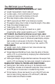
REAL WORLD CERTIFIERTM A whole new world of testing possibilities! MODEL RWC1000 USER’S GUIDE ★ ★ TEST D DISPLA Y AN S S ★★ CAT 3,5,5E,6 CA B CABLE CATEGORY *DIGITAL TEST 3* 5* EXIT 5E* 6* REVIEW Revision 4 CATEGORY LE
Limited Warranty The manufacturer warrants to the original consumer that this product is in good working order for a period of one year from the date of manufacture or date of purchase. During this period the product will be repaired or replaced without charge for either parts or labor. The warranty does not cover damage caused by improper use or abuse including connecting to high voltage. Repair or replacement as provided under this warranty is the exclusive remedy of the purchaser.
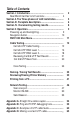
Table of Contents Section I. Introduction........................................................ 2 Real World Certifier list of functions........................ 4 Section II. The Three phases of LAN installation............. 5 6 Section III. Faceplate description...................................... Section IV. Documenting testing results......................... 8 Section V. Operation........................................................... 9 Powering up and backlighting...............................
Section I. Introduction Over half of all network problems are caused by faulty cables. And with network speeds exponentially increasing, the need for affordable, sophisticated test equipment is more apparent than ever before. The Real World Certifier (RWC) and Network Tester is break-throughtechnology that brings cable and network certification and testing to a whole new level of reality.
What is Real World Certification? Real World Certification means that a UTP cable passed a prescribed battery of tests and is therefore not likely to cause problems later.
The RWC1000 List of Functions UTP CABLES. Real World Certification Level 1 tests: ✔ Length measurement of each cable pair. ✔ Locates opens, shorts and distance to the fault. ✔ Locates split pairs and the distance to the split. ✔ Wire map. Graphs cables internal pairing. ✔ NEXT (near end) and FEXT (a far distance) crosstalk. ✔ Propagation delay (time for data to travel the length of the cable). ✔ Skew (time delay between pairs). ✔ Cable typing. CAT 3, 5, 5E, 6.
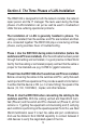
Section II. The Three Phases of LAN Installation The RWC1000 is designed for both the network installer, the network repair person and the IT manager. The tests used during the three phases of LAN installation can just as well be used to troubleshoot LANs that are suffering operational problems. The installation of a LAN is generally handled in phases. The cabling is installed; then the switches and PCs are installed; and then all is connected together.
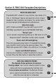
Section III. RWC1000 Faceplate Descriptions. RWC1000 MAIN UNIT The MAIN UNIT connects to any Cat 5/6, coax cable or 10, 100, or 1000 Base-T device and performs a host of tests needed for their installation and repair. For certain tests, it can be inserted inline between two LAN devices. Main Unit Jacks LEFT, COAX and RIGHT: Use the LEFT jack for UTP TESTING. Use RIGHT jack for NETWORK TESTING. ➊ ➋ "Printer" port Use to transfer stored testing data (up to 250 tests) to a PC. Requires Excel®.
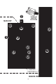
➋ RJ45/COAX ADAPTER FOR PROBE MAIN UNIT ➋ ➋ ➊ ➌ ➏ ➍ ➍ ➎ ➎ ➎ 9V BATTERY COMPARTMENTS REMOTE PROBE 7 ➐
Section IV. Documenting Testing Results The Real World Certifier includes 3 ways to document your test results. 1) A custom tablet can be used to fill in the test results (included). 2) "PASSED" stickers can be applied to wall outlets and LAN devices to Real World Certify their capability (included). 3) Printer Memory that stores test results for up to 250 Real World Certification tests, basic UTP tests and coax tests for later printing (requires a PC with Excel®).
Section V OPERATION Powering up and backlighting REAL WORLD CERTIFIER REVISION 800K1 SEL BACK LITE ON Backlight selection screen (lighting the LCD display) TURNING ON: Press the power button (PWR) and release to turn ON the tester. The "backlighting" screen appears (above). Pressing the select (SEL) button while this screen is present turns on LCD lighting ("backlighting"). Backlighting is important when working in dim light but shortens battery life.
The Main unit's navigation button How to navigate through the Real World Certifier screen: PWR. Power ON/OFF (see prior page for backlighting). SEL (SELECT). Press to perform task. Appears as on LCD. The UP arrow. Appears as on LCD. The DOWN arrow. Appears as on LCD. The SELECT button's function always selects the task. But the function of the UP and DOWN arrow buttons may change with each screen.
Main Menu RWC1000 Menu CAT 5/6 UTP COAX CABLE NETWORK PORTS PRINTER MEMORY EXIT SCROLL SEL This menu is the gateway to all of the RWC1000's tests. Scroll the cursor with the down arrow button and press SELECT to perform the task. CAT5/6 UTP: Test and Real World Certify UTP cables with or without LAN devices (hubs, switches, PCs) connected. Perform basic cable tests on UTP cables. Tone UTP cables. Move the cursor to CAT 5/6 UTP and press SELECT. Page 12.
CAT 5/6 UTP CAT 5/6 UTP Cable Testing Main Menu UTP Cable Testing Main Menu SELECT TEST: RW CERTIFY UTP BASIC TEST UTP TRACER TONES ON EXIT SCROLL SEL RW CERTIFY ("RWC") UTP: Move the cursor to RW CERTIFY UTP and press SELECT to start RWC Level 1 testing of a cable. RWC tests have 2 levels: Level 1 uses the Main Unit and Remote Probe to perform the Basic Cable Tests (listed below)... plus Speed parameter testing (10, 100, 1000MB) and Cable Category Testing (CAT 3, 5, 5E, 6).
RW CERTIFY UTP Perform Real World Certification Level 1 (UTP cables) and Level 2 (UTP cables and LAN devices) UN-COIL CABLE PLUG OPEN CABLE INTO LEFT PLUG DO NOT USE PROBE EXIT TEST Press down arrow button after cable is connected Follow the instructions. Only an uncoiled cable will give you accurate test results. At this point in the testing, the far end of the cable should not be connected to any device. Note: If the cable is connected to a device you will be alerted to check the far end of the cable.
CAT 5/6 UTP CAT 5/6 UTP Cable Testing / RW CERTIFY / LEVEL 1 SELECT CABLE PATCH 20' MIN SOLID 20' MIN Stranded or Solid wire selection screen EXIT SCROLL SEL The Real World Certifier has the unique ability to test both cables constructed of stranded wire (commonly called "patch" cables) and solid core wire. Scroll to select the cable and press SELECT. How to tell the difference: If the cable is installed in a wall, it is almost certainly a solid core wire.
Testing progress is shown on the screen Any problems will be displayed (See appendix C) TESTING CABLE TEST FOR DATA *SPLITS 12> 36> 45> 78> TDR NEXT FEXT SPEED TEST PAIRS 12> 36> 45> 78> During this phase of testing, information about length, opens, shorts, split pairs, crosstalk, cable category and speed is being gathered and computed. If there are no cable problems, testing continues until you are prompted to connect the Remote Probe and perform the Wire Map.
CAT 5/6 UTP CAT 5/6 UTP Cable Testing / RW CERTIFY / LEVEL 1 Testing is halted until the Remote Probe is connected. PLUG IN PROBE AT FAR END OF CABLE TRACE TONES ON EXIT The REMOTE PROBE is required for the WIRE MAP to be constructed. Plug the Remote Probe into the far end of the cable. Tracer tones have been turned ON to help locate cables in crowded areas (press the TRACE button on the Remote Probe and hold it close to the cable to follow the tone).
RWC Level 1 final screen (when you see this, Level 1 is completed and available for review) <<< PASSED >>> *DIGITAL TEST 3* 5* 5E* 6* EXIT REVIEW/SAVE When the above screen appears, the Level 1 RWC is complete. If you select REVIEW/SAVE, you will enter the Test Results Option Screen. To discard the test results immediately, select EXIT. Test results option screen REVIEW TEST SAVE READINGS RWC TEST PORT EDIT TEST NAME EXIT SCROLL SEL REVIEW TEST: View results from the Level 1 test.
CAT 5/6 UTP CAT 5/6 UTP Cable Testing / RW CERTIFY / LEVEL 2 RW CERTIFY UTP LEVEL 2 Perform Real World Certification Level 2 (UTP cables and LAN devices) If you have selected to continue with Real World Certification Level 2, this screen appears. PLUG IN PORT GIG PORT MAY RW CERTIFY TO 10M 100M 1 GIG EXIT CERT 2 Real World Certification Level 2 adds to the battery of tests conducted in Level 1 by testing the cable with real live data. The source of this data can be any hub, switch or PC.
Testing Link Pulses from a Gigabit device 12> 10M 100M FULL GIGABIT FULL 36> 10M 100M FULL GIGABIT FULL EXIT DETAILS Testing Link Pulses from a 100MB device 12> TESTING LINKS 36> 10M 100M HALF EXIT DETAILS The first step in the Level 2 process is to read the link pulses of the LAN device and determine its advertised capability. Every LAN device broadcasts its capability in terms of speed, duplex and other features (termed "advertised" capabilities) to other LAN devices.
CAT 5/6 UTP CAT 5/6 UTP Cable Testing / RW CERTIFY / LEVEL 2 Data Signal Levels: Immediately following the link pulse test, the Main Unit tests the data signal levels from the LAN device. The levels are not displayed at this time but are available during Review. RWC Level 2 final screen (when you see this screen, Level 2 is completed and available for review). RW CERTIFIED 1 GIG 10 100 1000 EXIT REVUE/SAVE When the above screen appears, the Level 2 RWC is complete.
CAT 5/6 UTP TEST REVIEW Review the readings from the most recent test or store the readings in Printer Memory. To review past readings stored in the memory see page 39. CABLE CATEGORY *DIGITAL TEST Cable Category is the first screen of many that are stored 3* 5* EXIT 5E* 6* REVIEW The "Cable Category" is universally accepted as the speed capability of the cable. Cat 3 was the original twisted pair cable that connected 10MB networks together. Then came Cat 5 (used in networks up to 100 MB).
CAT 5/6 UTP CAT 5/6 UTP Cable Testing / RW CERTIFY / REVIEW RW Certification Level 1 Speed Projection REAL WORLD CERTIFIED TO 100M 10 100 1000 MENU REVIEW Real World Certification Level 1 displays the projected speed capability of the cable. The graph is a result of thousands of measurements used to project the speed of the cable. This is one of the most useful and money-saving displays.
LENGTH = 201' DELAY 304NS PASS SKEW 3NS PASS Length / Timing summary screen MENU REVIEW Length: The length of the shortest cable pair (in feet). 330' is the longest cable allowed by the 802.3 standard. The Real World Certifier can test cables up to 1250' in length. Propagation delay: The time it takes for a data signal to travel the length of the cable (in nanoseconds). An abnormally long propagation delay indicates the cable is "too slow" for the application.
CAT 5/6 UTP CAT 5/6 UTP Cable Testing / RW CERTIFY / REVIEW RWC Level 1 Pass / Fail Summary Screen DELAY OK NEXT OK SPLIT OK PATCH MENU SKEW OK FEXT OK MAP OK TOL 94% REVIEW DELAY OK: The propagation delay of the cable is within specification. See page 23 for the definition of delay. SKEW OK: The skew of the cable is within specification. See page 23 for the definition of skew.
specifications at a given speed. One percent is barely passing. 100 percent is maximum tolerance. Tolerance is largely cable length driven. The longer the cable is, the less the tolerance. However, lower Category cables eat up tolerance faster than higher Category cables. If Tolerance is below 15%, you may wish to consider using a repeater, hub or switch to shorten the cable run. This is especially true if you are in a "noisy" environment (large electromechanical machines, etc.).
CAT 5/6 UTP CAT 5/6 UTP Cable Testing / RW CERTIFY / REVIEW P ro p a g a t i o n and skew (per pair) screens 12> 309NS 36> 309NS 45> 305NS 78> 305NS MENU 12> 4NS 36> 4NS 45> 0NS 78> 0NS MNEU DELAY DELAY DELAY DELAY REVIEW SKEW SKEW SKEW SKEW REVIEW Timing data per pair: The next two screens give you the timing of the propagation delay and skew for each pair in the cable. Large variations between pairs indicate trouble.
The following screen only appears if Certification Level 2 was performed. Signal levels of real live data from a gigabit switch DATA MIN 12 36 45 78 MENU REVIEW DATA MIN Signal levels of real live data from a 100MB switch 36 MENU REVIEW The signal level screen is one the most powerful tools used during Level 2 certification. It is a live signal attenuation display. If the level is below the DATA MIN line, you may experience faulty transmissions.
CAT 5/6 UTP CAT 5/6 UTP Cable Testing / RW CERTIFY / REVIEW The following screen only appears if Certification Level 2 was performed. Real World Certification Level 2 summary screen RW CERTIFIED 1 GIG 10 100 1000 EXIT REVIEW Real World Certification Level 2 displays the Real World certified Level 2 speed capability of the cable.
CABLE CATEGORY *DIGITAL TEST If you see this screen again, you are reviewing the same data again 3* 5* EXIT 5E* 6* REVIEW Select EXIT at any time to stop the Review. If you select EXIT, you will be given the option to SAVE the test results with or without a NAME or to discard the results. Select REVIEW to continue reviewing. REVIEW TEST SAVE READINGS RWC LEVEL 2 EDIT TEST NAME EXIT SCROLL SEL Test results option screen "EXIT" See page 35 for SAVING and NAMING instructions.
CAT 5/6 UTP CAT 5/6 UTP Cable Testing / BASIC TEST UTP BASIC TESTING OF UTP Test UTP for opens, short, split pairs, length and distance to fault. UTP Cable Test Main Menu RW CERTIFY UTP BASIC TEST UTP TRACE TONES ON EXIT SCROLL SEL BASIC TEST UTP: Move the cursor to BASIC TEST and press SELECT to test a UTP cable for length, opens, shorts, split pairs (plus distance to these faults) and wire map. BASIC TEST UTP is a quick test and does not perform Real World Certification.
accurate length measurement. At this point in the testing, the far end of the cable should not be connected to any device. Note: If the far end of the cable is connected to any device it will notify you to check the far end of the cable.When ready to proceed, press ( TEST). Error Messages: If there is a problem that stops the test from proceeding, one of the following error messages will be displayed: CABLE IS ACTIVE: There is an active network port on the far end of the cable.
CAT 5/6 UTP CAT 5/6 UTP Cable Testing / BASIC TEST UTP UTP pairs and length are displayed. Select MAP + TRACE for wiremap and tones 12> 203' 36> 203' 45> 201' 78> 200' EXIT MAP + TRACE Remote Probe LEDs. The Remote Probe needs to be connected only for a brief period. Flashing LED(s) indicate the test is progressing. A steady LED indicates the test is completed. LEDs This saves you an extra trip to retrieve the probe. If LED(s) continue to flash the cable, the cable has a wiring problem.
COAX CABLE TESTING Test coax cable for opens, short, length and distance to fault. CAT 5/6 UTP COAX CABLE NETWORK PORTS PRINTER MEMORY EXIT SCROLL SEL Select COAX CABLE from Main Menu COAX CABLE TESTING: Move the cursor to COAX CABLE and press SELECT to test a coax cable for length, opens, shorts (plus distance to these faults). Wire map and toning is also available from this menu. COAX CABLE test is a quick test and does not perform Real World Certification. Test results can be stored in Printer Memory.
COAX CABLES COAX CABLE TESTING Connect the coax cable to the F connector on the Main Unit and select coax. The test begins. 12> 105' COAX EXIT MAP + TRACE At the beginning of the test, the far end of the cable should not be connected to anything. The coax pair (pins 1 and 2) and length are displayed. Select MAP + TRACE for wiremap and tones Coax Wire Map A correct wire map for a coax cable.
NAMING / SAVING TEST RESULTS Naming and Saving test results start at this screen REVIEW TEST SAVE READING RWC TEST PORT EDIT TEST NAME EXIT SCROLL SEL REVIEW TEST: Review test results before they are SAVED. After reviewing the test results you can return to this screen. SAVE READINGS: Store the results from the latest test in PRINTER MEMORY for later printing. The next sequential Reading Number (1-250) is automatically assigned along with any NAME that you created (see EDIT TEST NAME below).
NAMING / SAVING TEST RESULTS EDIT NAME Select EDITTEST NAME to create a custom name for the test results. Do this before saving the test in memory. REVIEW TEST SAVE READING RWC TEST PORT EDIT TEST NAME EXIT SCROLL SEL To NAME a reading, you must first complete any of the RWC1000's cable tests. At the end of the test, press the DOWN arrow (labeled "REVIEW/SAVE" or "SAVE") and the above screen appears. Select EDIT TEST NAME. Note: Creating a name (EDIT TEST NAME) for a test result is optional.
NAMING / SAVING TEST RESULTS Naming your tests TEST NAME line A maximum 16 character name appears here. W WXYZ MENU #012 SELECT CHAR The UP and DOWN arrows rotate the "LETTER LOOP" to the right and left. The SEL key copies the letter to the TEST NAME LINE. Create a label: Rotate the letter loop until the letter or command desired appears at the leftmost of the display and press the SEL button. Exercise the "Rotating Letter Loop" It's the best way to learn how to create a name. Exercise #1.
NAMING SAVING TEST RESULTS EDIT NAME Exercise #2. Create the test name "TEST", then erase: Step 1: Position the LETTER LOOP so "T" is the leftmost letter on the screen (use the UP and DOWN arrow keys to position the letter "T" at the left side of the LCD display). Step 2. Press the SEL key, copying the "T" up to the TEST NAME line. Now do the same for "E", "S" and "T". Step 3. If you make a mistake, try the letter loop's "cursor characters" ( ). They allow you to control the cursor's postion.
REVIEWING PRINTER MEMORY PRINTER MEMORY Review or Erase stored readings (memory stores up to 250 readings). PRINTER MEMORY: "Printer memory" is the storage location for all SAVED test readings. It can store the results of up to 250 RWC tests (Level 1 and/or combined Level 1 and Level 2), Basic UTP tests and coax tests for later printing. After each test is conducted, you have the option to REVIEW, SAVE and/or NAME the test results (readings) in PRINTER MEMORY for later printing.
REVIEWING PRINTER MEMORY Review or Erase selection screen REVIEW MEMORY ERASE MEMORY EXIT MEMORY REVIEW: Use the UP and DOWN arrow to find the reading you wish to review in Printer Memory. Press SEL to review. "BLANK TEST NAME" indicates a name has not been created for the test. ERASE: Selecting the ERASE function erases all of Printer Memory. There is no way to selectively erase readings. This screen verifies that you wish to erase all of Printer Memory.
PRINTING FROM A PC Transfer the test readings from the Main Unit to the PC using the supplied cable, driver and software (requires Microsoft® Excel®) USB micro B plug USB port PC with Excel and a USB port RWC1000 with up to 250 stored readings STEP 2: TRANSFERRING TEST READINGS (RWC TO PC): 1) Connect the RWC to a USB port on your PC and turn the RWC ON. 2) Run the "RWC1000.xls" spreadsheet (found on the RWC software CD). RWC1000.
PRINTING FROM A PC STEP-BY STEP INSTRUCTIONS FOR USING EXCEL: After you have installed the driver and connected the RWC1000 to the PC, launch Excel. Select FILE, OPEN and select RWC1000.xls (either from your RWC software CD or hard drive). Microsoft Excel Excel asks you if you wish to "Enable macros". Select "Enable macros". Say "No" if asked if you want to open as a "Read Only" file. The workbook you are opening contains macros. Some macros may contain viruses taht could be harmful to your computer.
PRINTING FROM A PC Microsoft Excel Press the Import Readings button next. It downloads data from the serial port specified in the drop down box. Press OK. Import Readings Download from network tester successful! OK Error messages: If Excel says "Please select a serial port with a network tester connected" or "No network testers found", communication is not established with the RWC's USB port.
PRINTING FROM A PC PRINTING When satisfied, press Finish. The spreadsheet named "RWC1000.XLS" will appear. One cable test reading occupies one worksheet. You can do anything with this spreadsheet as would with any Excel spreadsheet (save it under a different name, change the names in the cells, etc.). When you are ready to print, select FILE, PRINT and in the PRINT WHAT dialog box select ALL. All of the cable test readings will print (one per page).
PRINTING FROM A PC Typical RWC1000 printout Note: If Level 2 testing was not performed, the Data Signal Levels and the RW Certification #2 charts will have no data. Reading: Cable# 1 Length Delay Skew Patch/Solid 25 ft.
Network Testing Menu NETWORK PORTS Display the advertised and negotiated speeds of LAN devices and view the signal levels of real live data. "USE RIGHT JACK" ALERT SCREEN NETWORKS CAT 5/6 UTP COAX CABLE NETWORK PORTS PRINTER MEMORY EXIT SCROLL SEL USE PLUG <> HUBVOLTAGES DAMAGE LEFT PLUG EXIT TEST PORT NETWORK PORTS (USE RIGHT JACK) Select Network Ports to display the capabilities of a LAN device.
Network Testing / SCAN ONE PORT SCAN ONE PORT MONITOR INLINE SEND BEACON EXIT SCROLL SEL SCAN ONE PORT USE RIGHT JACK 47 NETWORKS SCAN ONE PORT: Move the cursor to SCAN ONE PORT and press SELECT if you wish to display the advertised capability of a LAN device. You can connect to any LAN device using a patch cable or any cable of your choosing. The signal data levels of all active pairs will also be displayed.
Network Testing / SCAN ONE PORT Testing Link Pulses from a Gigabit device 12> 10M 100M FULL GIGABIT FULL 36> 10M 100M FULL GIGABIT FULL EXIT DETAILS Testing Link Pulses from a 100MB device 12> 36> 10M 100M HALF EXIT DETAILS The first step in the scanning process reads the link pulses of the LAN device and display the advertised capability. LAN devices broadcast their capability in terms of speed, duplex and other features (termed "advertised" capabilities) to other LAN devices.
Network Testing / SCAN ONE PORT Signal levels of real live data from a gigabit switch DATA MIN 12 36 45 78 EXIT DETAILS Signal levels of real live data from a 100MB switch DATA MIN 36 EXIT DETAILS The signal level screen is a powerful tool. It is a live signal attenuation display. If the level is below the DATA MIN line, you may experience faulty transmissions. If the signal is well above the DATA MIN line, you have plenty of "headroom". ) key to continue.
Network Testing / MONITOR INLINE SCAN ONE PORT MONITOR INLINE SEND BEACON EXIT SCROLL SEL MONITOR INLINE RWC's RIGHT JACK (PoE PROTECTED) RWC's LEFT JACK (NOT PROTECTED) NETWORKS MONITOR INLINE: Move the cursor to MONITOR INLINE and press SELECT if you wish to view the negotiated results between two LAN devices. Note: Data communication can take place while the Main Unit is inline between two devices but after the negotiation is complete. The MONITOR INLINE TEST is methodical and mostly automatic.
Network Testing / MONITOR INLINE Screen-by-screen instructions to perform INLINE testing. Follow the steps and wait for the RWC1000 directions. The tester will tell you when it is time for the next step. UNPLUG ALL PORTS. When the RWC1000 senses that no ports are connected to the tester, it will begin. UNPLUG ALL PORTS EXIT PLUG IN 2 PORTS. Plug in both devices using the "LEFT" and "RIGHT" sockets of the RWC1000. PLUG-IN 2 PORTS PC =>LEFT PLUG HUB=> RIGHT PLUG EXIT CAPABILITY SCREEN.
Network Testing / MONITOR INLINE NEGOTIATED GIGA BIT FD The Negotiated Speed of the link is automatically displayed. OK TO SEND DATA MENU The MONITOR INLINE TEST is complete. Data can be transmitted between the two LAN devices without removing the tester. NETWORKS Note: Most network ports negotiate to the highest possible data rate. Some ports will negotiate to a maximum of the last data rate used.
Network Testing / SEND BEACON SEND BEACON Locate cable drops by lighting a link LED SCAN ONE PORT MONITOR INLINE SEND BEACON Scroll down and select SEND BEACON EXIT SCROLL SEL USE RIGHT JACK (PoE PROTECTED) PORT BEACON: Use the Port Beacon to locate cable connections in crowded areas. To activate the port beacon, move the cursor to PORT BEACON and press SELECT. The Port Beacon is a link pulse that the Main Unit sends to the receiving device every 3 seconds.
Appendix A. Straight coupler When installing or troubleshooting a LAN, you might need a straightthru cable coupler. The RWC1000's Main Unit jacks makes it easy. The tester must be OFF to utilize this feature. APPENDIX Straight-thru coupler Note: If you suspect one of the devices is capable of sourcing PoE voltage, connect the device to the RIGHT jack. The RIGHT jack is protected from PoE voltage.
Appendix B. Ping and TCP/IP debugging tools What is TCP/IP: TCP/IP is set of standards first developed by ARPA (USA DOD’s Advance Research Projects Agency) that define how information is routed over the Internet. And because of its internet popularity, TCP/IP is the most popular protocol operating over twisted pair cabling... and therefore is the most popular protocol used by Ethernet (the standard for local area networking).
APPENDIX Because TCP/IP is so common, Windows and many UNIX systems have built-in tools to help you debug TCP/IP network problems. These debugging programs are executed at the command line prompt of the operating system (see the end of this section for more information about the command line). ping The most popular TCP/IP debugging program is called “ping” (after the name given to the operation of submarine sonar devices).
The Ping program has endless uses. Ping an address (as above): If you get a response using the IP address but do not get a response using the DNS address, there must be a problem with the DNS system. If you suspect this, try another debugging program "nslookup". On the command line enter nslookup followed by the DNS name (enter nslookup www. bytebrothers.com) and see if the IP address is displayed. If it is, your DNS appears to be working correctly.
you do not know its DNS name or IP address use ipconfig (below). To learn all of the ping command’s option, enter ping /?. APPENDIX ipconfig USE: Determine the IP address and other related information about a workstation. Enter ipconfig /? at the prompt to display the options possible with this command. The two most common entries: ipconfig and ipconfig /all. EXAMPLES OF USE: I want to ping a remote server but I do not know its ip address. Go to the server and at the command line prompt enter “ipconfig”.
Additional information: The web has many interesting articles on network troubleshooting and also numerous sites that feature a glossary of terms. Use your favorite search engine and search for Pinging, Pinging Devices, Network management, Network Monitoring Tools, Network Testing, etc. 59 APPENDIX Executing troubleshooting programs from the command line All of the programs discussed must be executed from the command line of your operating system.
Appendix C. Examples of cable faults A good cable: A cable that passes its first set of cable tests will have summary screen similar to this: LENGTH = 201' DELAY 304NS PASS SKEW 3NS PASS Length / Timing summary screen of a good cable EXIT REVIEW APPENDIX Bad cable (Split pair): If errors are found, they will be displayed. Here are some examples of screens with bad cables.
Bad cable (Near end short): The error is displayed as follows: Bad cable: Near End Short 12> ------- SHORT 36> 26' OPEN 45> 25' OPEN 78> 26' OPEN EXIT DETAILS Bad cable: Far End Short 12> 36> 45> 78> EXIT 27' 26' 25' 26' SHORT OPEN OPEN OPEN DETAILS OPENs in cable pairs generate errors in both in SKEW tests and in wire map tests. The following example shows a 200’ cable with a break in the middle on pair 78. The following is the first screen to show a problem.
is that the cable LENGTH is only shown as 98’. Press DETAILS and continue the tests. All will become clear when cable map is displayed. Here is a sample cable map. APPENDIX Bad cable: Wire map of open pair 12> 199' 36> 202' 45> 202' 78> 98' EXIT = = = <12 = = = <36 = = = <45 = = = OPEN DETAILS The sample map clearly shows the problem. There is an OPEN at 98’ on pair 78>. The SKEW was so large because the timing pulses travel about 200’ on pairs 12, 36, and 45, but only travel 98’ on pair 78.
Appendix D. Making a correct UTP cable As mentioned above, twisted pair cable has separate pairs of wires twisted together to minimize crosstalk. If a wiring error is made and one pair of wire is “split” with another ("split pairs"), the excess crosstalk will most likely keep the link from operating properly. To make a proper cable, first choose a twisted pair cable that is adequate for your application. For instance, CAT 5E cable for 100MB and 1000MB applications.
RJ45 Connectors (sockets and plugs): The Base-T Standard uses RJ45 sockets and plugs. The RJ45 socket has 8 pins. The pins are numbered 1 to 8. Looking at the socket with insertion key facing down, pin number 1 is to the left. PLUGS SOCKETS 1 8 8 8 1 1 1 8 APPENDIX PIN NUMBERS EIA/TIA 568B STRAIGHT THRU PIN # PIN# WIRE COLOR 1 1 Orange/White 2 2 Orange 3 3 Green/White 6 6 Green 4 4 Blue 5 5 Blue/White 7 7 Brown/White 8 8 Brown Colors: The first color is the base color on the cable.
© 2010 Byte Brothers, Inc. www.bytebrothers.com Network Test and Certification 7003 132nd Place SE, Newcastle, WA 98059 USA +1.425.917.8380 ● FAX +1.425.917.8379 ● cs@bytebrothers.