Smart CAT5 Switch 108 and 116 User Guide 1111 W. 35th Street, Chicago, IL 60609 USA www.tripplite.com/support Copyright ©2012 Tripp Lite. All rights reserved.
SMART CAT5 SWITCH – 108/116 Table of Contents 1. Welcome ................................................................................................................................ 4 2. Introduction........................................................................................................................... 5 2.1 Features............................................................................................................................................. 5 2.2 System components ....
USER GUIDE 4.2.9 Security ....................................................................................................................................... 22 4.2.10 The OSD HELP window – F1..................................................................................................... 23 4.2.11 Scanning computers– F4 ........................................................................................................... 24 4.2.12 Tuning – F5 ...................................................
SMART CAT5 SWITCH – 108/116 6.7.2 Getting the current status............................................................................................................. 38 6.7.3 Communication Error message.................................................................................................... 38 6.7.4 Electricity failure........................................................................................................................... 39 7. RICC SUN keyboard emulation...................
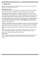
USER GUIDE 1 . We l c om e Thank you for buying the Smart CAT5 Switch system. This system is produced by Minicom Advanced Systems Limited. Technical precautions This equipment generates radio frequency energy and if not installed in accordance with the manufacturer’s instructions, may cause radio frequency interference. This equipment complies with Part 15, Subpart J of the FCC rules for a Class A computing device.
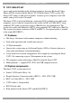
SMART CAT5 SWITCH – 108/116 2 . I nt r od u c t i on Access and control multiple multi-platform computers from one Keyboard Video Mouse (KVM) console with the Smart CAT5 Switch (Smart CAT5) system. The Smart CAT5 comes in 108 and 116 models. Connect up to 8 computers to the 108 model, and up to 16 to the 116 model.
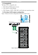
USER GUIDE 2.3 Compatibility The Smart CAT5 is compatible with: PS/2, SUN and USB computers/servers VGA, SVGA, or XGA monitors DOS, Windows, LINUX, UNIX, MAC and all other major operating systems 2.4 The Smart CAT5 system configuration Figure 1 illustrates the basic configuration of the Smart CAT5 system. Workstation SMART CAT5 SWITCH 116 www.minicom.
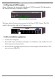
SMART CAT5 SWITCH – 108/116 2.5 The Smart CAT5 models Figure 2 illustrates the front panel of the Smart CAT5 116 model. The 108 model is the same but with only 8 columns of LEDs. MINICOM SELECT SMART CAT5 SWITCH Selected CPU on 1 2 3 4 5 6 7 8 9 10 11 12 13 14 15 16 Figure 2 Smart CAT5 116 front panel The figure below illustrates the rear panel of the Smart CAT5 116 unit. The 108 model is the same but with only 8 Computer ports. www.minicom.
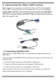
USER GUIDE 3 . C o n ne c t i n g t he S m a r t C AT 5 s ys t e m Each computer/ server is directly connected to the Smart CAT5 via the appropriate ROC or RICC using CAT5 cable in a star configuration. The system can contain a mixture of RoCs and RICCs. No external power is needed at the remote ROC/RICCs. The ROC/RICCs draw their power from the computer’s keyboard port (ROC/RICC PS/2, SUN) or from the USB port (ROC/RICC USB). The figures below illustrate the ROC PS/2 and ROC USB.
SMART CAT5 SWITCH – 108/116 NetServer tc2100 To Keyboard port Mouse Keybd 100T To Mouse port Parallel Serial A RICC PS/2 Video Serial B To Video port SCSI CAT5 cable to Smart CAT5 Computer port PCI 33Mx32b PCI 33Mx32b PCI 33Mx32b PCI 33Mx32b Figure 6 RICC PS/2 connections 3.2 Connecting a ROC/RICC USB The ROC/RICC USB supports Windows 98 SE and later, MAC, SUN, SGI and all modern Linux distributions. The connections for ROC/RICC USB are exactly the same.
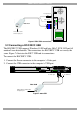
USER GUIDE 3.3 Connecting a RICC SUN Figure 8 illustrates the RICC SUN and its connections. To connect the RICC SUN: 1. Connect the Screen connector to the computer’s Video port. 2. Connect the Keyboard connector to the computer’s Keyboard port. To Video port To Keyboard Port RICC SUN CAT5 cable to Smart CAT5 Computer port Figure 8 RICC SUN 3.4 Connecting the CAT5 cables 1. Connect one connector to the ROC/RICCs RJ45 port. 2. Connect the other connector to one of the Smart CAT5’s Computer ports. 3.
SMART CAT5 SWITCH – 108/116 3.6.1 Avoiding general rack mounting problems Elevated operating ambient temperature The operating ambient temperature of the rack environment may be greater than the room ambient when installing into a closed or multi-unit rack assembly. So install the equipment in an environment compatible with the maximum rated ambient temperature. Reduced airflow Install the equipment in a rack in such a way that the amount of airflow required for safe operation is not compromised.
USER GUIDE Screw the bracket into the side of the unit Screw to the rack here Figure 10 Connecting the L-shaped bracket 3.6.3 Rack mounting the RICCs You can attach the RICCs to a server rack or computer using the Velcro strips provided. Or connect it using the bracket provided. The figure below illustrates the bracket.
SMART CAT5 SWITCH – 108/116 With the Smart CAT5 116 model, connect up to up to 256 computers through cascading. A lower level Switch must have a different hotkey to display its OSD than a higher level switch. Changing the OSD display hotkey is explained on page 18 below. P110 SD KVM Console Top level Smart CAT5 Switch ww w.minicom.
USER GUIDE 4 . O pe r a t i n g t he S m a r t C AT 5 s ys t e m Switch between the connected computers by either The front panel Select buttons Keyboard hotkeys The OSD (On Screen Display) or Control software The OSD is also the place to adjust various settings as explained below. When switching computers the illuminated LED of the top bank indicates which computer is currently selected. 4.1 The keyboard hotkeys To switch to the next computer forwards press Shift then, +.
SMART CAT5 SWITCH – 108/116 Port number appears here C=Computer Instruction keys Figure 13 OSD Main window 4.2.1 Navigating the OSD To navigate up and down use the Up and Down arrow keys. To jump from one column to the next (when relevant) use the Tab key. To exit the OSD or return to a previous window within the OSD press Esc. 4.2.2 Selecting a computer To select a computer: 1. Navigate to the desired computer line. Or, type the port number of the desired computer. 2. Press Enter.
USER GUIDE Figure 14 Settings window Note! When the OSD is password protected (explained below) only the Administrator has access to the F2 settings window. 4.2.4 The General settings With the GENERAL line highlighted, press Enter. The General settings window appears see Figure 15. Figure 15 General Settings window From this window you can do the following: 4.2.4.1 Security The OSD comes with an advanced password security system that contains 3 different security levels.
SMART CAT5 SWITCH – 108/116 4.2.4.2 Administrator (Status A) The Administrator can: Set and modify all Passwords and security profiles Fully access any computer Use all OSD functions 4.2.4.3 Supervisor (Status S) The Supervisor can: Fully access any computer Access the following OSD functions only –F4 Scan, F5 Tune and F6 Moving the Confirmation label. 4.2.4.4 User (Status U) There are 6 different Users in the Smart CAT5 system.
USER GUIDE 4.2.4.6 Displaying the OSD of cascaded switches When you have cascaded Smart CAT5 switches, a lower level Switch must have a different OSD display hotkey than a higher level switch. (See page 12.) The hotkeys can be any of the following: Shift, Shift (default) Ctrl, Ctrl Ctrl, F11 Print Screen To change the top level hotkey: 1. Navigate to the HOTKEY line. 2. Choose a different hotkey than the Shift, Shift hotkey of the lower level Switches.
SMART CAT5 SWITCH – 108/116 To change the Serial port setting: 1. Navigate to the Serial port line. 2. Toggle between the options using the Spacebar. 4.2.4.9 Changing the Keyboard language In the OSD the names of the computers can be written in 3 different languages – English (EN), German (DE), and French (FR). The keyboard is preset to English; this can be changed as follows: 1. Navigate to the Keyboard language line. 2. Toggle between the options using the Spacebar. 4.2.4.
USER GUIDE 4.2.6.1 Editing the computer name In this window you can edit the computer names with up to 15 characters. When you have a cascaded CAT5 KVM Switch connected to a Computer port give the switch a distinct name. See Figure 16. To erase a character: Select it and press the Spacebar. Blank spaces remain in place of the erased character. To erase an entire line: Place the cursor at the beginning of the line. Keep the Spacebar depressed until the line is erased. 4.2.6.
SMART CAT5 SWITCH – 108/116 Figure 17 Time settings window 4.2.7.1 Scan (SCN) - Label (LBL) - Time out (T/O) SCN - In the SCN column, change the scan period. LBL - In the LBL column, change the display period of the OSD label showing which computer is currently accessed. T/O - When password protection is activated you can automatically disable the Management keyboard, mouse and screen after a preset time of non-use. Set this Timeout period in the T/O column. To set the above periods: 1.
USER GUIDE Figure 18 Users settings window There are 3 different access levels. These are: Y – Full access to a particular computer. Plus access to the F4, F5 and F6 OSD functions V –Viewing access only, to a particular computer (No keyboard/mouse functionality) N – No access to a particular computer – A TIMEOUT label appears if access is attempted To give each user the desired access level: 1. Navigate to the desired computer line and User. 2. Toggle between the options using the Spacebar. 4.
SMART CAT5 SWITCH – 108/116 Figure 19 Security settings window The ‘T’ column on the right hand side stands for Type of password. There can only be 1 Administrator password, 1 Supervisor password, and 6 User passwords. To change a user name or password: 1. Navigate to the desired line and column. 2. Type a new user name / password. User authentication is done solely via the password there is no security significance to the names. By default the User Profile settings are full access. 4.2.
USER GUIDE 4.2.11 Scanning computers– F4 Where necessary adjust the scan time in the Time Settings window, see above. To activate scanning: 1. Press Shift twice to open the OSD. 2. Press F4. Your screen displays each active computer sequentially, with the Scan label appearing in the top left corner. To deactivate scanning: Press F4. 4.2.12 Tuning – F5 You can tune the image of any remote computer screen from the Select Computer window. To adjust the screen image: 1.
SMART CAT5 SWITCH – 108/116 Input the DDC information of the monitor connected to the Smart CAT5 switch into the memories of all connected ROC/RICCs when first installing system. To input the DDC information: 1. Disconnect the Video cable of all ROC/RICCs from the computers. 2. Press Shift twice to open the OSD. 3. Press F10. “Please wait” flashes a few times and disappears. The monitor’s DDC information is sent to all ROC/RICCs. 4. Reconnect the Video cable of all ROC/RICCs. 4.2.14.
USER GUIDE 5 . U s i n g t he Co n t r ol s of tw a r e As an alternative to the OSD, you can operate the system with the Control software located on our website www.minicom.com in the Support section on the Smart CAT5 Switch Upgrades page. With the OSD you operate the system and view the computer screens on the same monitor. The Control software requires 2 monitors: 1 for the software and 1 to view the computer screens.
SMART CAT5 SWITCH – 108/116 5.3 Installing and running the Control software Note! The system must be fully connected BEFORE running the Control software. Failure to first connect the system will lead to the software working in demo mode. 1. Download the software from www.minicom.com and install it on your computer. Once installed, a shortcut icon appears on the Desktop . 2. Double-click the icon to run the software. Or choose Start / Programs / Smart CAT5 RS232 Control / Smart CAT5 RS232 Control.
USER GUIDE 5.3.2 Computer icons Icon Meaning Computer is connected and switched on Computer is switched off or unconnected Computer that you are presently connected to Connected and switched on computer with a Local Workstation attached and presently being used locally. After remaining idle for the Timeout period, it changes to yellow. When you first open the Control window the software automatically gets the status of the system, including the security access settings. 5.3.
SMART CAT5 SWITCH – 108/116 5.3.5 Selecting a computer To select a computer: Click on the computers icon. The system switches to that computer. The connected icon appears with a red background . Control and monitor the selected computer from the keyboard and mouse connected to the Smart Switch. 5.3.6 The toolbar buttons The toolbar buttons are explained below. 5.3.
USER GUIDE 5.3.11 The Edit menu You can edit all OSD fields. Edit the following from the Edit menu. Logo Passwords Settings 5.3.12 Logo and Passwords You can edit the logo that appears at the top of the OSD window. You can also edit the names and passwords for the Administrator, Supervisor and 6 Users. 1. Edit the Logo and Passwords by choosing them from the Edit menu. See figures below. Figure 24 Logo Figure 25 Names and passwords 2. Make the desired changes. 3. Click OK. 5.3.
SMART CAT5 SWITCH – 108/116 Here you can edit all the data that can be edited in the OSD. This includes: Scan times, Timeout, Confirmation label display time, Keyboard type/mode, User access, Password mode, Autoskip mode, and Switch/System hotkey. These features are explained in the OSD section of this Appendix. To edit a setting: 1. In the Computer List, select the desired computer or group of computers. 2. Make the desired changes. 3. Check the Select box next to the changed setting. 4. Click OK. 5.3.13.
USER GUIDE 5.4 Password protection When the Smart CAT5 system is password protected, the Control software behaves in exactly the same way as the OSD. You must type in the required password to access the Control software. The access you gain depends on the security status – exactly as with the OSD. To change the security access, close and reopen the Control software, and type in the different password. 5.4.
SMART CAT5 SWITCH – 108/116 6 . U p gr a di n g t he S m a r t C AT 5 f i r mw a r e With the Smart CAT5 Update software program you can upgrade the firmware for the: OSD Manager ROC/RICCs Smart CAT5 Update enables you to add new features and fix bugs in a quick and efficient manner. You can also return the OSD to the factory default settings via the Update software. Install the Smart CAT5 Switch Update on any computer, even one not part of the Smart CAT5 system. 6.
USER GUIDE 6.4 Installing the software Download the Update software and install it on your computer. 6.4.1 Connecting the RS232 Serial cable To run the software, connect the RS232 Serial cable to the computer containing the Update software, and to the Smart CAT5 Switch. See page 26. 6.5 Starting and configuring the Smart CAT5 Update 1. Start the Smart CAT5 Update software by double-clicking the icon on your desktop , or choose Start/Programs/Smart CAT5 Switch Update/Smart CAT5 Switch Update.
SMART CAT5 SWITCH – 108/116 Button or Box Function Cancels selected function System time Displays device status Name of Update file 2. To change the Com Port from the Options menu choose Com Port. The Com Port Dialog box appears. See Figure 29. Figure 29 Com Option box 3. Choose the Com Port the RS232 Serial cable is connected to and click OK. 6.5.1 Verifying the version numbers Before upgrading the firmware, you must first verify which firmware and hardware versions you have. 6.5.1.
USER GUIDE 6.5.1.2 Smart CAT5 Manager version number To verify the Smart CAT5 version number: 1. In the Switch Unit box, check the Smart CAT5 Manager option. 2. Click box. . The firmware version number appears in the Switch Unit 3. Click box. . The hardware version number appears in the Switch Unit 6.5.1.3 ROC/RICC version number To verify the RICC version number: 1. Before you can check a ROC/RICC, you must uncheck the Switch Unit box options. 2. Check one or more or all of the ROC/RICCs. 3.
SMART CAT5 SWITCH – 108/116 Figure 30 Open box 4. Open the file. 5. Click Start. The Smart CAT5 Switch Update flashes the firmware. On completion the firmware version number appears. 6. Check that the updated version number is correct by pressing . 6.6 Restoring factory settings You can restore the OSD to the factory settings from the Update software. Note! All changes made (passwords, access rights, names etc.) will be removed.
USER GUIDE 6.7.1 Resetting the units Resetting can be done from the Update software or from the Smart CAT5 switch. Resetting through the Update software Reset the software for the Smart CAT5 Manager or ROC/RICCs when for example the unit hangs or when the mouse fails to work properly. Resetting is done via the Serial port, and avoids the need to shut down the computer. NOTE! The Reset function does not affect the parameters of the unit settings. To reset the Switch or RICC units: 1.
SMART CAT5 SWITCH – 108/116 6.7.4 Electricity failure When the electricity fails while updating the Smart CAT5 firmware, do the following: If the electricity fails during the firmware update of the Switch, a Communication Error message appears. Simply resume the firmware update by opening the folder that contains the firmware update file and continue from there. If the electricity fails during the firmware update of the ROC/RICCs a Not Responding or Upgrade Error message appears.
USER GUIDE 7 . R I C C S U N k e yb o a r d e m ul a t i on By default the RICC SUN supports US English keyboard emulation. It also supports German and Swiss German keyboard emulation. You can download the appropriate keyboard emulation firmware from our website www.minicom.com in the Support section on the Smart CAT5 Switch Upgrades page. Upload the firmware to the RICC SUN. Other language keyboard emulations will be posted on the Minicom Web site as they become available.
SMART CAT5 SWITCH – 108/116 8 . U S B / S UN C om b o k e ys The connected PS/2 keyboard does not have a special SUN keypad to perform special functions in the SUN Operating System environment. So when a ROC/RICC USB or SUN is connected to a SUN computer, the ROC/RICC emulates these SUN keys using a set of key combinations called Combo keys. See the table below.
USER GUIDE 9 . Te c hni c a l s p e c i f i c a t i o ns Operating systems and Platforms DOS, Windows, LINUX, UNIX, MAC and all other major operating systems Mouse PS/2, Wheel mouse, Intellimouse, 5-button mouse Resolution 1600x1200@75Hz System cable CAT5/ 5E/ 5+/ 6/ or 7 cables. FTP or UTP 2x4x24 AWG solid wire Transmission distance RICCs up to 10m/33ft. RoCs up to 30m/99ft. Smart CAT5 Switch Dimensions – 108/116 port 215.0 x 122.0 x 41.5mm / 8.46 x 4.80 x 1.
SMART CAT5 SWITCH – 108/116 9.1 Safety The device must only be opened by an authorized Minicom technician. Disconnect device from AC mains before service operation! 9.
USER GUIDE 201204196 • 933193 44