y nt ion y for a Lite nty a r p a ar trat e todaE Trip /warr W is -lin RE om g n F .c Re ster owin aipplite gi to .tr Re ce ww an ! w ch uct od pr Owner’s Manual SmartOnline Single-Phase 5kVA, 6kVA & 10kVA ™ Intelligent True On-Line UPS Systems (Rackmount/Tower) For all UPS system modules (power module, transformer module and battery module). Select UPS system modules may include separate instruction or warning sheets which should be used in conjunction with this manual.
Important Safety Warnings SAVE THESE INSTRUCTIONS. This manual contains important instructions and warnings that should be followed during the installation and maintenance of all Tripp Lite SmartOnline Rackmount/Tower UPS Systems and their batteries. UPS Location Warnings • Install your UPS indoors, away from excess moisture or heat, direct sunlight, dust and conductive contaminants. • Install your UPS in a structurally sound area. Your UPS is extremely heavy; take care when moving and lifting the unit.
Mounting (Rack) Mount your equipment in either a 4-post or 2-post rack or rack enclosure.The user must determine the fitness of hardware and procedures before mounting. If hardware and procedures are not suitable for your application, contact the manufacturer of your rack or rack enclosure. The procedures described in this manual are for common rack and rack enclosure types and may not be appropriate for all applications.
Mounting (Tower) All modules can be mounted in an upright, tower position when used with optional adjustable base stands, sold separately from Tripp Lite (model #: 2-9USTAND). When mounting modules on the adjustable base stands, make sure that the power module's control panel is towards the top. Also, if you are installing a transformer module, place it between the power module and its battery module.
Features There are three separate UPS system modules available from Tripp Lite (a power module, a transformer module and a battery module) used in a variety of combinations. Familiarize yourself with the location and function of the features on each module before installing and operating your UPS system. The power module is the only module which includes front panel features. 11 Power Module Front Panel Controls 10 9 8 7 6 12 12 1 2 3 4 5 1.
Features (Rear Panel) see page 9 for feature descriptions 5kVA Power Module 11 12 12 7 8 9 6 10 3 13 14 13 5kVA Transformer Module 25 19 25 26 24 25 5kVA Battery Module* 28 * The 5kVA Power Module is shipped with a Battery Module which is not expandable; however, the Power Module is fully compatible with Tripp Lite Battery Modules which are expandable (Tripp Lite model # BP240V10RT-3U, sold separately) if extended runtime is required.
Features (Rear Panel) see page 9 for feature descriptions 5 6kVA Power Module 4 1 2 7 8 9 6 10 3 6kVA Transformer Module 16 15 20 17 19 20 6kVA Battery Module* * Expandable Battery Module (Tripp Lite model # BP240V10RT-3U) shown. Depending on the model ordered, the 6kVA Power Module may have been shipped with an expandable Battery Module (like the one shown above) or one which is not expandable.
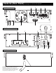
Features (Rear Panel) see page 9 for feature descriptions 5 6 10kVA Power Module 4 3 7 8 9 1 10 21 10kVA Transformer Module 16 2 15 20 18 10kVA Battery Module * Expandable Battery Module (Tripp Lite model # BP240V10RT-3U) shown. Depending on the model ordered, the 10kVA Power Module may have been shipped with an expandable Battery Module (like the one shown above) or one which is not expandable.
Features (Rear Panel) continued Power Module Feature Description 1. Output Terminal Block (6kVA and 10kVA models only): Use these terminals to connect your power module to your equipment or to the transformer module. Unscrew and remove the cover over the block for access. 2. Input Terminal Block (6kVA and 10kVA models only): Use these terminals to connect your power module to utility power or to the transformer module. Unscrew and remove the cover over the block for access. 3.
Features (Rear Panel) continued 23. Input Voltage Select Switch (6kVA and 10kVA models only): Use this switch to set the transformer module's input voltage (either 200V AC, 208V AC or 240V AC). See “Connection” section for details. 24. AC Output Receptacles (5kVA models only): Accepts direct plug-in connection of NEMA 5-15P or NEMA 5-20P equipment plugs. 25.
Connection continued Connection Combination #1: Power Module (5kVA) + Battery Module 1 5kVA Power Module Shown Plug your equipment into the power module. Plug your equipment power cords A directly into the power module's AC Output Receptacles B . B A 1 2 Plug the power module into a wall receptacle. Plug the power module's AC input cord C directly into a wall receptacle D providing 200/208/220/230 or 240V AC utility power. C D 2 3 Connect the battery module to the power module.
Connection continued Connection Combination #2: Power Module (5kVA) + Transformer Module (5kVA) + Battery Module 1 5kVA Power Module Shown Plug the transformer module into the power module. Plug the transformer module's connector cable A directly into either of the 5kVA power module's AC Output 2 Receptacles B . NOTE: this cable should only be plugged into the 5kVA power module. B 1 2 Plug your equipment into the power module and transfer module.
Connection continued Connection Combination #3: Power Module (either 6kVA or 10kVA) + Battery Module(s) 1 6kVA Power Module Shown Hardwire the power module to your equipment. A Using a screwdriver, remove the top of the box A covering the power module’s input and output terminals. Pass a user-supplied cable through the terminal box’s left knockout B and connect it to the power module’s output terminals. Connect the other end of the cable to your equipment.
Connection continued Connection Combination #4: Power Module (6kVA) + Transformer Module (6kVA) + Battery Module(s) 1 Connect the power module to the transformer module. Using a screwdriver, remove the entire box A covering the power module’s input and output terminals. Remove the screws on either side of the terminals. Grip the terminals B and slide them out until you can view the cable connector release tab C . Press the tab down and pull on the cables to release them from the internal connector D .
Connection 4 continued Select the transformer module’s input voltage. Using a screwdriver, remove the panel covering the transformer module’s Input Voltage Select Switch J . Set the switch to match your facility’s input voltage. Then, use the power module’s front panel switches to configure input voltage on the LCD Display (see “Configure your UPS’s input and output” in the “Power ON/OFF” section on page 14).
Connection 3 continued Hardwire the transformer module to a utility power source. Pass a user-supplied cable through the box’s middle knockout F and connect it to the transformer module’s input terminals. Connect the other end of the cable to a utility power source. Replace the top of the boxes covering the power module’s and transformer module’s terminals. NORMAL BY PASS F 3 4 Select the transformer module’s input voltage.
Optional Connection The following connections are optional. Your UPS system will function properly without these connections. RS-232 Serial Communication Connection Use the included cable to connect the power module’s “RS-232” port to the communication port on your computer. This will allow full network monitoring and control of your UPS system. Install on your computer the Tripp Lite PowerAlert Software appropriate to your computer’s operating system.
Power ON/OFF (5kVA models only) 1. Configure your UPS’s input and output: Put your UPS power module into setup mode by holding down both of its scroll buttons ( A and B ) at once. Scroll through the setup options (using A or B ) and select the appropriate setting for each of the following options using the “SELECT” button B . • Input & Output Voltage: Select 200, 208 or 240 VAC. • Output Frequency: Your UPS will autoselect 50 or 60 Hz to match the input.
Power ON/OFF (6kVA and 10kVA models only) 1. Configure your UPS’s input and output: Put your UPS power module into setup mode by holding down both of its scroll buttons ( A and B ) at once. Scroll through the setup options (using A or B ) and select the appropriate setting for each of the following options using the “SELECT” button B . • Input & Output Voltage: Select 200, 208 or 240 VAC. • Output Frequency: Your UPS will autoselect 50 or 60 Hz to match the input.
Manual Bypass Operation (6kVA and 10kVA models only) (for power module maintenance or replacement) The following procedure only applies to UPS system configurations that include a 6kVA or 10kVA transformer module. The procedure details how to service or replace the power module while supplying equipment connected to the transformer module with utility power.
Operation Startup Self-Test When you turn the UPS ON, it will enter Diagnostic Mode and perform a brief self-test lasting about 15 seconds. The results of the self-test are shown on the LCD screen in the sequence below.
Operation continued Normal Operation During normal operation, the first line of your LCD Display shows which operating mode your UPS is in: Online, Economy, On Battery, or Bypass. Online mode: The UPS provides AC power while utility power is available and switches to On Battery mode instantly (zero transfer time) if AC power is interrupted. Economy mode: The UPS provides AC power at high efficiency while utility power is available and switches to On Battery mode quickly if AC power is interrupted.
Operation continued Bypass Messages While in Bypass Mode, the UPS monitors its input voltage and passes that input power along to connected equipment. The UPS will not provide battery backup in Bypass Mode. If the output voltage deviates from an acceptable range (between 15% higher and 20% lower than nominal), the UPS displays the condition on its LCD and stops supplying output power to its load.
Storage, Service, Warranty, Warranty Registration and Insurance Storage Before storing your UPS, turn it completely OFF. If you store your UPS for an extended period of time, recharge the UPS batteries for 4 to 6 hours once every three months. Note: after you connect the UPS to utility power, it will automatically begin charging its batteries. If you leave your UPS batteries discharged for an extended period of time, they will suffer a permanent loss of capacity.
Specifications The models listed below include a power module, one or two battery modules, and a transformer module. All models include all three types of modules, with the exception of hardwired (HV) models, which do not include transformer modules. Depending on the model ordered, the included battery module may be either expandable or nonexpandable.
1111 W. 35th Street, Chicago, IL 60609 USA 773.869.1234 (USA) • 773.869.1212 (International) www.tripplite.