
Automatic Power System Owner's Manual


9
Switches, Indicator Lights
& Other Features
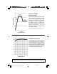
(See Diagram 10, p. 48 to locate the following switches, indicator lights and other features. 10.1
shows the UniPlug Universal Plug Adaptor [included with APS INT 512 models] which accepts
most worldwide plug configurations; 10.2 shows the plug and cordset. Note: 10.21=ground,
10.22=neutral, 10.23=line 1, 10.24=detachable line cord. 10.3 shows the “Configuration Dip
Switches” located on the bottom of the unit.)
Switches
1. “Operating Mode” Switch
This switch selects the APS operating mode (either “CHARGE ONLY/REMOTE”, “AUTO”, or
“OFF”. See “Equipment Connection” for the optimum switch setting.
2. “CONFIGURATION” DIP Switches
These four switches must be set for the type of battery your APS will be connected to and the voltage
range outside of which your APS will switch to battery power. The Battery Type DIP Switch #1 setting
must match the type of batteries you connect or your batteries may be degraded or damaged over
an extended period of time. Most loads will perform adequately when your APS’s High AC Voltage
Point DIP Switch #2 is set to 257V and its Low AC Voltage Point DIP Switches #3 and #4 are set to
181V. Set your APS above or below these points, however, to minimize frequent battery operation
caused by momentary high/low line voltage swings which have little effect on equipment operation.
(See “APS Installation” and Diagram 1 on page 46.)
Indicator Lights
3. “LINE”
This green light will turn continuously ON whenever connected equipment is receiving utility-supplied
AC power. It will flash intermittently when utility power is present and your APS's Operating Mode
Switch is set to “Charge Only/Remote” to warn you that the APS's inverter is OFF and that the APS
WILL NOT provide battery backup during blackouts, brownouts or overvoltages.
4. “INV”
This red light will turn continuously ON whenever connected equipment is receiving battery-supplied
AC power (during a blackout, brownout or overvoltage while connected to utility power or when
connected to batteries during vehicular operation).
5. “LOAD”
This red light will turn continuously ON when the APS’s load is between 80% and 110% of capacity.
The light will flash intermittently when the APS's inverter shuts down due to a severe overload or
overheating. If this happens, turn Operating Mode Switch OFF. Remove overload. Let the unit cool.
You may then turn the APS ON again.
200002089 APS Manual 230 Volt Version.p65 5/31/00, 4:30 PM9