
Standard KVM Switch Owner's Manual


5
Controls and Connections
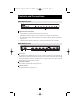
B004-008 Front View:
1 Lighted Port Selection Button
• Lights GREEN to indicate which ports have been selected.
• Lights RED to indicate which ports are connected to a computer and powered on.
• An unlit button indicates that no computer is connected or that the connected computer is
not power on.
• A flashing button indicates which port is currently selected in the auto-scan mode.
B004-008 Rear View:
Power Jack
The optional power adapter plugs in here. The switch is designed to be non-powered (no
external power required). It draws the necessary power from the connected CPUs through
the Keyboard/Mouse connection. External power is required if the CPUs do not provide
sufficient power (operation will be erratic).
Console Port Section
Your monitor, keyboard and mouse plug in here.
CPU Port Section
The cables from the PCs plug in here.
1
1
1
3
1
2
3
21
200508040 93-2465 B004-008 OM.qxd 8/10/2005 2:58 PM Page 5