pr ch Re R WA od an gis EG R uc ce te I R t! to r o ST A ww w nl R NT w. in ine AT Y I tri a pp FR tod ON lit EE ay e. co Trip for m p a /w Li ar te ra nt y Owner’s Manual NetCommander IP Cat5 Multi-User KVM Switch Models: B072-016-IP2, B072-016-IP4, B072-032-IP2, B072-032-IP4 1111 W. 35th Street, Chicago, IL 60609 USA • www.tripplite.com/support Copyright © 2013 Tripp Lite. All rights reserved. All trademarks are the property of their respective owners.
Table of Contents Legal Notice . . . . . . . . . . . . . . . . . . . . . . . . . . . 3 3. Conducting a Remote Session . . . . . . . . . . . 34 3.1 Starting a Remote Session . . . . . . . . . . . . . . . . . . . . 34 1. Product Overview . . . . . . . . . . . . . . . . . . . . . 3 3.2 Remote Session Toolbar . . . . . . . . . . . . . . . . . . . . . . 35 1.1 Features and Benefits . . . . . . . . . .
Legal Notice This manual and the software described in it are furnished under license, and may be used or copied only in accordance with the terms of such license. The content of this manual is provided for informational use only, and is subject to change without notice. It should not in and of itself be construed as a commitment by Tripp Lite, which assumes no responsibility of liability for any errors or inaccuracies that may appear in this book.
1. Product Overview 1.2 Terminology The following table describes terms used in this guide. Term Definition Target Server The computer/server that is connected directly to the KVM, and which is accessed via the local console or by a Client Computer running a remote session. Client Computer A computer running a remote session, which is used to access computer/servers or devices connected to the KVM.
1. Product Overview • If an extension cord is used with this device, make sure that the total ampere rating of all products used on the cord does not exceed the extension cord ampere rating. Make sure that the total of all products plugged into the wall outlet does not exceed 15 amperes.
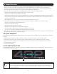
1. Product Overview The NetCommander IP back panel is illustrated in the figure below. Note: The figure below shows the back panel for a B072-032-IP2 and B072-032-IP4, but the back panel will be functionally the same for all models, with the only difference being the number of server ports. 3 4 5 7 1 2 Element 6 Functionality 1 Power Outlets The KVM features dual-power supplies, so that if power to one fails, the other takes over. The power cords included with the KVM connect to the unit here.
1. Product Overview 1.9 Connecting the System The figure below illustrates the NetCommander IP system overview. Note: The figure below shows a B072-032-IP4 4-User installation. Set up is the same for all models, with the only difference being the number of simultaneous users supported, and the number of ports. 1. Make sure that power to all the devices you will be connecting has been turned off. 2. Connect a VGA cable from the monitor to the HD15 (VGA) port on the back of the KVM. 3.
1. Product Overview To set the IPv4 address via the local console OSD: 1. From the local console, press the left [Shift] key twice to open the OSD. 2. Press the [F2] key to open the Settings menu. 3. In the Settings menu, press the [Tab] key until the DHCP field is highlighted. Press the [Spacebar] key to toggle the DHCP field from Enabled to Disabled. 4.
1. Product Overview To set the IP address via the Web Configuration Interface: Note: • Before logging on the first time, verify that you have the latest Java installed on your computer (Java 1.6 or higher is required). If not, you can download and install Java from http://www.java.com/en/download/index.jsp. • Only SSL connections are allowed, so you must start the IP address with HTTPS, not HTTP. 1.
1. Product Overview 6. Click on the Configuration icon at the top of the screen to pull up the KVM’s Configuration screen. It opens with the Device tab displayed. 7. There are two LAN sections in the Device tab, one for IPv4 and one for IPv6. For IPv4, you have the options of automatically assigning an address via DHCP server (default) and manually assigning an address.
2. Web Configuration Interface The NetCommander IP can be accessed in two ways; locally via the local console OSD, or remotely via the Web Configuration Interface. This section of the manual details the Web Configuration Interface, which can be used to access the computer/servers and other devices connected to the KVM, as well as to configure the KVM’s settings and accounts. 2.
2. Web Configuration Interface 2.2 Web Configuration Interface Layout The Web Configuration Interface contains the following main elements: 1 2 3 4 Element 1 Header Bar Description The Header Bar is at the very top of the screen, and displays the following: XA general Window Icon, which you can double-click on to close the Web Configuration Interface screen, or click once on to open a menu with options for restoring, moving, sizing, minimizing, maximizing, or closing the screen.
2. Web Configuration Interface 2.3 My Targets Section The My Targets section of the Web Configuration Interface is the first page that is displayed upon logging into the KVM remotely. This section is where users remotely access the connected computers/servers and serial devices. When accessing the My Targets section, only the connected computers/servers and devices that the logged-in account has access to are displayed in the Data Pane.
2. Web Configuration Interface The following table describes the columns found in the My Targets section Data Pane. Server Name The Server Name column displays all of the Target Servers and Serial devices that are accessible to the logged in account. The Server Name for each port can be changed in the Configuration section of the Web Configuration Interface (see the Switch Configuration section of this manual for details).
2. Web Configuration Interface 2.4.1 Firmware Upgrade To perform a firmware upgrade, follow these steps: Note: Depending on the type of firmware upgrade, the following settings may be erased: User settings, KVM switch settings, mouse and video adjustments, and RS232 settings. The network settings remain intact. For more information, refer to the firmware release notes. 1. Download the firmware upgrade file from www.tripplite.com/support. 2. Save the firmware upgrade file on the Client Computer. 3.
2. Web Configuration Interface In addition to the KVM firmware, you can upgrade the SIU firmware to take advantage of new features. 1. Download the firmware upgrade file from www.tripplite.com/support. 2. Save the firmware upgrade file on the Client Computer. 3. Login to the Web Configuration Interface and navigate to the Configuration section. In the Configuration section’s toolbar, click on the icon. The RoCs Upgrade page appears. 4.
2. Web Configuration Interface 2.4.2 Backup/Restore Using the Backup/Restore function in the Configuration sections toolbar, you can back up all configuration data and restore it at a later date. To back up data: 1. In the toolbar, click on icon. The Backup/Restore Data page appears. 2. In the Backup to file field, click the Browse button to open up the Enter file name to backup to screen. 3.
2. Web Configuration Interface To restore data: 1. In the toolbar, click on icon. The Backup/Restore Data page appears. 2. Click the Browse button next to the Restore data from file field, and then navigate to and select the KVM backup. 3. Click the Restore button to restore the KVM configuration. 4. When complete, click the OK button to exit the Web Configuration Interface and perform a KVM reboot. 2.4.
2. Web Configuration Interface 6. When the SSL certificate has been installed, a prompt appears to let you know the installation was successful, and that the KVM will be rebooted. Click the OK button to exit the Web Configuration Interface and reboot the KVM. 2.4.4 Device The Device tab in the Configuration section allows administrators to configure the KVM’s Device ID, LAN, and SNMP settings. The settings in this page are described in the following section.
2. Web Configuration Interface Configuring the SNMP settings: This section of the Device tab allows you to configure the KVM so that notifications can be sent to a SNMP server when a LAN port or power socket fails. Upon receiving notification of the failure, LAN or power redundancy are enabled. Note: If both LANs or power sockets fail, a message cannot be sent to the SNMP server.
2. Web Configuration Interface To edit an account: 1. In the Users page, select an account from the list and click the Edit button. The Edit User page appears. 2. Change the Permission and/or Access as required. Checking the Block checkbox next to the Access field blocks an account from accessing the KVM, but keeps its information stored in the KVM. This way, if you ever want to reactivate the account, all you have to do is go back in and uncheck this box. 3. To change the password, click .
2. Web Configuration Interface 2.4.6 Switch Configuration The Switch Configuration tab allows unique names to be assigned to each port, to help distinguish the Target Servers that are connected to them. To edit a port name: 1. From the Configuration section, click on the Switch Configuration tab. The Switch Configuration page appears. 2. To change the name of a port, highlight the current server name, and type a new name. 3. Click the Save button at the top of the screen to save your changes.
2. Web Configuration Interface 2.4.7 User Targets By default, administrators are allowed access to all servers. However, you must define the access rights of each user account to the following: • Target Access – To initiate a remote session for the corresponding port. • Virtual media access – To use the Virtual Media functionality when in a remote session for the corresponding port. To configure User Targets: 1. From the Configuration section, select the User Targets tab. The User Targets page appears.
2. Web Configuration Interface 3. In PDU Name, type an appropriate name for the PDU you are adding. 4. The Type drop-down menu provides a list of PDUs that are supported by the NetCommander IP. Select your PDU from this list. Based on your selection, the number of PDU outlets is displayed in the Outlets field. 5. In the Address section, enter in the type of IP Address appropriate for your PDU; IPv4, IPv6, or Host. Note: When using a host name for an IPv6 address, add the prefix udp6: to it.
2. Web Configuration Interface 2.4.9 Power Outlets Once a PDU is added to the KVM via the Power Devices section, you need to assign a NetCommander IP Target Server port to one of the ports on a PDU to be able to Power Cycle it, or turn its power Off/On. For Target Servers with dual power supplies, you can assign multiple PDU ports to the same KVM port. In this case, power to both of the Target Server ports will be managed at the same time. To configure the power outlets: 1.
2. Web Configuration Interface 2.4.10 Serial Ports The Serial Ports page is where you configure the settings of the serial device(s) that you have connected to the KVM. (see the Serial Pinout section in this manual for the pinout information) To configure the serial port settings: 1. From the Configuration section, select the Serial Ports tab. The Serial Ports page appears. 2.
2. Web Configuration Interface 2. In the Account Blocking section: • In the Block after field, enter in the number of unsuccessful login attempts that will be allowed in a given time period. This time period is set in the attempts within (hr:min) field. Enter into this field the time in hours and minutes. • In the Block account field, you can select the length of time that an account will be blocked for if it exceeds the number of unsuccessful login attempts.
2. Web Configuration Interface 2.4.12 Authentication The Authentication page allows you to set up remote authentication via RADIUS and/or LDAP/S server. From the Configuration section, select the Authentication tab to open this page. Enable Authentication Methods – The section at the top of the Authentication page determines which types of authentication are enabled, and what priority they take when authenticating a user.
2. Web Configuration Interface • To add an LDAP/S server to the list, click on the Add button to bring up the Add LDAP Server screen. • Enter the IPv4, IPv6, or Host address for your LDAP/S server in the corresponding field. • Select the Port number that is used by the server. The default port number is 389 for LDAP/TLS servers and 636 for LDAPS servers. • Select from one of three encryption methods to use: No encryption, SSL, or TLS extension. • Click the OK button to add the server to the list.
2. Web Configuration Interface • Search Base – The Search Base field should be populated with the location in the Active Directory in which the search is taking place. • Search Password – The Search Password field should be populated with the password for the user account that is being used to query the Active Directory. • Confirm Password – Re-enter the password into this field to confirm that you have entered it correctly.
2. Web Configuration Interface Access Rights Permission String – In order for access rights to be assigned in User or Group authentication mode, a permission string must be entered into the directory attribute that is assigned to each User or Group. The name of this attribute must be entered into the Access Rights Attribute field in the Mode section of the Authentication page. See below for an explanation of how the permission string needs to be formatted.
2. Web Configuration Interface • Enter and re-enter a shared secret according to the one specified in the RADIUS server. • Click the OK button to add the server to the list. • Servers can be edited or deleted by highlighting them in the list and clicking on Edit or Delete. They can be re-ordered according to their priority by highlighting them and clicking on Up or Down to move them in the list.
2. Web Configuration Interface 2. In the New Password field, type in a new password, according to the Password Policy set in the Security page of the Configuration section (see the Security section in this manual for details). 3. In the Confirm Password, retype the new password. 4. Click . The new password is saved in the system. 2.6 Events Section The Events section of the Web Configuration Interface allows administrator accounts to view a log of events that take place on the installation.
3. Conducting a Remote Session A remote session allows accounts IP access to computer/servers and serial devices connected to the KVM. In a remote session, accounts can access computers/servers, power cycle or turn power to a Target Server Off/On, virtually mount an .iso file, and configure the remote session settings. The sections that follow explain the features of a remote session, and how to use them. 3.1 Starting a Remote Session To start a remote session: 1.
3. Conducting a Remote Session 3.2 Remote Session Toolbar The NetCommander IP provides a toolbar that allows a remote session to be manipulated. The features on the toolbar allow you to toggle between accessible ports, adjust the video settings of the remote session, align the local and remote mouse pointers, etc.. When a remote session is initiated, the toolbar is displayed briefly in the top-center of the screen, and then collapses to display only a thin bar.
3. Conducting a Remote Session • Unmount ISO – The Unmount ISO feature disconnects an ISO virtual media file that has already been mounted. To unmount an ISO file: 1. Click on the action. icon in the remote session toolbar, and choose the Unmount ISO option. A prompt appears asking you to confirm the 2. Click Yes. The ISO virtual media file is unmounted from the remote server.
3. Conducting a Remote Session 4. In the Exclusivity section, check the Exclusive Session checkbox to prevent other accounts from accessing the Target Server port at the same time. By default, this checkbox is unchecked, and a remote session is initiated in Share Mode, which allows up to 5 accounts to log into a port at the same time (see the Shared Session section in this manual for details).
3. Conducting a Remote Session To manually adjust the video settings: 1. Click on the icon in the remote session toolbar, and choose the Advanced option. The Advanced window appears. 2. In the Brightness & Contrast section of the Advanced screen, use the corresponding scales to adjust the brightness and contrast of the displayed image. 3. In the Offset, Phase and Scale section of the Advanced screen, adjust the following settings accordingly: • In the H.
3. Conducting a Remote Session 3.2.5 Keys – Clicking on the Keys icon will display a list of predefined key sequences (e.g. Ctrl + Alt + Delete) that can be performed on the Target Server. By default, performing these key sequences on the Client Computer’s keyboard sends the command to the Client Computer. Opening the Keys menu and clicking on one of the predefined commands will send it directly to the Target Server.
3. Conducting a Remote Session To record a keyboard sequence: 1. Open the Special Key Manager window and click the Record New Custom Key button. The Record New Custom Key macro screen appears. 2. In the Label field, type a name for the new key sequence. 3. Click the Start Recording button. 4. On your keyboard, press the keys to include in the key sequence. The names of the pressed keys appear in the provided area as you type them. 5. When done with the sequence, click the Stop Recording button. 6.
3. Conducting a Remote Session 3.2.6 Mouse – Clicking on the Mouse icon allows you to select the Mouse Settings mode being used, as well as to manually adjust settings related to mouse synchronization. The following section describes the settings found via the Mouse icon and how to use them, as well as general tips for mouse synchronization and improving keyboard/mouse response time. To set the Mouse Settings mode: 1. Click on the icon in the remote session toolbar, and choose the Mouse Settings option.
3. Conducting a Remote Session To configure settings in Relative Mouse Position, OS-Specific mode: 1. Click on the icon in the remote session toolbar, and choose the Mouse Settings option. The Mouse Settings window appears. 2. Check the Relative Mouse Position, OS-Specific checkbox. Additional settings appear that allow you to manually configure the mouse settings according to your Target Server’s OS and mouse type. 3.
3. Conducting a Remote Session To align the mouse pointers: Note: The Align function is only available in the Mouse drop-down menu when the Mouse Settings mode is set to Relative Mouse Position. When logging into the KVM or accessing a new port, the local and remote mouse pointers may not be aligned. This does not always mean that they are not set up properly. Click on the Align feature in the Mouse drop-down menu of the toolbar to bring them together. 1.
3. Conducting a Remote Session 3.2.7 Server/Serial – Clicking on the Server/Serial icon displays a drop-down list of ports that are accessible to the currently logged-in account. Simply select a port to access it. 3.2.8 Full Screen – Clicking on the Full Screen icon (or pressing [Alt] + [Enter]) toggles full screen mode on/off. 3.2.9 Logout – Clicking the Logout icon closes your remote session, but does not log you out of the Web Configuration Interface. 3.
4. Local Console This chapter explains how to operate the NetCommander IP via the local console. The local console allows you to access connected computer/servers, configure the KVM’s network settings, and to configure some more basic settings specific to local access. To display the OSD: 1. From the local keyboard, press the left Shift key twice. The OSD Main window appears. Lines with sun icons in the PM column show active computers/ servers.
4. Local Console 4.3 Power Management As with the Web Configuration Interface, you are able to perform power management functions via the local console. The power management functions available to you are described below. Note: In order to perform power management actions on a port, it must be configured to match a power outlet of a power device that has been added to the KVM.
4. Local Console To set the IPv4 address via the local console OSD: 1. From the local console, press the left [Shift] key twice to open the OSD. 2. Press the [F2] key to open the Settings menu. 3. In the Settings menu, press the [Tab] key until the DHCP field is highlighted. Press the [Spacebar] key to toggle the DHCP field from Enabled to Disabled. 4. Pressing the [Tab] key to navigate to the additional fields, type in the desired IP Address, Subnet Mask, Gateway, and DNS Server Address (Optional).
4. Local Console Changing the Hotkey: By default, the hotkey combination used to open the OSD is [Shift] + [Shift]. You can change this hotkey in the F2 – SETTING menu to use any of the following. Note: The left [Shift] hotkey must be used; the right [Shift] key will not work. If you set the hotkey to [Ctrl] + [Ctrl] or [Ctrl] + [F11], the left [Ctrl] key must be used. • [Shift] + [Shift] • [Ctrl] + [Ctrl] • [Ctrl] + [F11] • [Print Screen] + [Print Screen] To change the hotkey: 1.
5. Serial Port Pinout Note: When connecting a Cisco device, use Cisco rolled cable. Serial Port 1: Serial Port 2: Pin 1: RTS Pin 1: RTS Pin 2: DTR Pin 2: DTR Pin 3: TX Pin 3: TX Pin 4: GND Pin 4: GND Pin 5: GND Pin 5: GND Pin 6: RX Pin 6: RX Pin 7: DSR (pins 7 and pin 2 are shorted inside the unit) Pin 7: DSR Pin 8: CTS Pin 8: CTS 6.
6. Security Certificate Installation 3. Click on the Certificate error message to display the Certificate Invalid prompt. 4. Click on the View certificates option at the bottom of the prompt to redirect to the Certificate screen.
6. Security Certificate Installation 5. Click on the Install Certificate button to bring up the Certificate Import Wizard, then click the Next button. 6. Select the option to Place all certificates in the following store, then click the Browse button. Highlight the Trusted Root Certification Authorities folder. 7. Click OK. You will be redirected back to the previous screen. Click Next, followed by Finish. Upon clicking Finish, you will be prompted to confirm installation of the certificate. 8.
6. Security Certificate Installation Java Security The following steps apply to Internet Explorer 9 and Java version 1.7.0_45, but may also be used with other Web browsers and Java versions. Note: You may need to run Internet Explorer as an Administrator to install the security certificate. 1. Open your Web browser and login to the KVM. If the KVM certificate has not yet been installed in the browser, a URL bar with a Certificate error message will appear.
6. Security Certificate Installation 3. In the Details tab page, click on the Copy to File button. The Certificate Export Wizard appears. 4. Click Next, accepting the default values until you get to the File to Export page. 5. Click the Browse button to navigate the location you want to save the certificate file, and then type a name into the File name field. Click Next to go back to the File to Export screen, where the file path will be entered.
6. Security Certificate Installation 6. Click the Next button, followed by the Finish button on the next page to complete export of the KVM certificate. 7. Navigate to your computer’s Control Panel window and open the Java Control Panel. 8. Click on the Security tab, then click the Manage Certificates button. 9. In the Certificate type drop-down menu at the top of the screen, select the Secure Site option. 10.
7. Technical Specifications Specification Description Operating systems Target Server – Windows and Linux Client computer – Windows with Internet Explorer, Firefox, or Chrome browsers. Linux with Firefox or Chrome browsers. Max Resolution 1920 x 1080 Distance from Switch to SIUs Up to 100 ft. (30 m.
8. Video Resolution and Refresh Rates Hz 56 60 x 640x480 65 66 70 72 x x x x 75 x x 76 x x x 1024x768 x 85 86 x x 720x400 800x600 73 x x x x x x x x x 1152x864 x 1152x900 1280x720 x 1280x768 x 1280x960 x 1280x1024 x 1600x1200 x 1920x1080 x 1920x1200 x x x x x x x x 9.