pr ch re od an gi R W uc ce ste eg ar t— to r o is ra w w nli tra nty w in n w. a e tio tr i F to n pp R da : lit EE y f e. T o co ri r a m pp /w L ar ite ra nt y 201007212 93-2986.indb 1 Owner’s Manual DVI Over Cat5 Extender/Splitter Local Unit Models: B140-002 and B140-004 Remote Unit Models: B140-1P0, B140-1P0-WP, B140-1A0 and B140-1A0-WP 1111 W. 35th Street, Chicago, IL 60609 USA www.tripplite.com/support Copyright © 2010 Tripp1Lite. All rights reserved.
Package Contents All Units: • B140-002, B140-004, B140-1A0, B140-1A0-WP, B140-1P0 or B140-1P0-WP • Owner’s Manual B140-002, B140-004, B140-1A0 and B140-1A0-WP: • External Power Supply (Input: 100-240V, 50/60Hz, 0.5A Output: 5V, 2A) B140-002, B140-004 and B140-1A0: • Mounting Hardware B140-1A0-WP and B140-1P0-WP: • Mounting Screws • 110 Punchdown Tool B140-1A0 and B140-1A0-WP: • Screwdriver B140-004: • DVI Daisy-Chain Cable (1 ft.
Product Features continued • B140-1P0 and B140-1P0-WP remote units require no external power. • B140-1A0 and B140-1A0-WP remote units feature a built-in equalization control to adjust the video image. • Compatible with all operating systems, no software or drivers required. Optional Accessories • N001-Series Cat5e Snagless Patch Cables • N002-Series Cat5e Patch Cables • N020-01K-GY Gray Cat5e Bulk Stranded Cable – 1000 ft. • N022-01K-GY Gray Cat5e Bulk Solid Cable – 1000 ft.
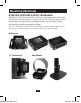
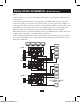
Mounting (Optional) B140-002, B140-004 & B140-1A0 Models: The B140-002, B140-004 and B140-1A0 come with mounting hardware that allows them to be mounted in a variety of ways. The following images show the different ways the included mounting brackets can be attached to the remote unit for different mounting methods. Note: The B140-004 can also be mounted to a Tripp Lite B132-004-RB 1U Rackmount Bracket. Up to 3 B140-004 local units can be connected to a B132-004-RB.
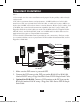
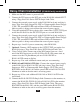
Standard Installation Notes: 1. Test to make sure the entire installation works properly before pulling cables through ceilings/walls. 2. To achieve maximum distance and performance, 24 AWG solid wire Cat5e/6 cable must be used. The use of stranded wire Cat5e/6 cable, or cable with a gauge (AWG) size higher than 24 AWG, will result in shorter extension distance. Higher gauge cabling, such as 26 AWG, has a more limited transmission capability than lower gauge cabling.
Standard Installation continued 4. Connect the external power supply to the B140-002 or B140-004 local unit and plug it into a Tripp Lite Surge Suppressor, PDU or Uninterruptible Power Supply (UPS). The green RJ45 LEDs and red Power LED on the B140-004 will illuminate to indicate power is being received from the external power supply. The green RJ45 LEDs on the B140-002 will illuminate to indicate power is being received from the external power supply. 5.
Daisy-Chain Installation (B140-004 only) Notes: 1) Test to make sure the entire installation works properly before pulling cables through ceilings/walls. 2) To achieve maximum distance and performance, 24 AWG solid wire Cat5e/6 cable must be used. The use of stranded wire Cat5e/6 cable, or cable with a gauge (AWG) size higher than 24 AWG, will result in shorter extension distance. Higher gauge cabling, such as 26 AWG, has a more limited transmission capability than lower gauge cabling.
Daisy-Chain Installation (B140-004 only) continued 1. Make sure the DVI source is powered-OFF. 2. Connect the DVI source to the DVI port on the B140-004 labeled INPUT using a Tripp Lite P561-Series DVI-D Single-Link Cable. 3. Connect the external power supply to the B140-004 local unit and plug it into a Tripp Lite Surge Suppressor, PDU or Uninterruptible Power Supply (UPS). The green RJ45 LEDs and red Power LED will illuminate to indicate power is being received from the external power supply. 4.
Daisy-Chain Installation (B140-004 only) continued 13. Repeat step 12 for each additional monitor you are connecting. 14. Turn on the power to the DVI source. The orange RJ45 LEDs illuminate on the B140-004 and B140-1A0 and the orange LED illuminates on the B140-1A0-WP to indicate the unit is receiving a signal from the source. The screen should now be displayed on the connected monitors. 15. If necessary, use the Equalization control on the B140-1A0 or B140-1A0-WP to adjust the video image.
Warranty & Warranty Registration 1-Year Limited Warranty TRIPP LITE warrants its products to be free from defects in materials and workmanship for a period of one (1) year from the date of initial purchase. TRIPP LITE’s obligation under this warranty is limited to repairing or replacing (at its sole option) any such defective products. To obtain service under this warranty, you must obtain a Returned Material Authorization (RMA) number from TRIPP LITE or an authorized TRIPP LITE service center.
Manual del propietario Extensor/divisor DVI sobre Cat5 Modelos de unidad local: B140-002 y B140-004 Modelos de unidad remota: B140-1P0, B140-1P0-WP, B140-1A0 y B140-1A0-WP English 1 Français 21 201007212 93-2986.indb 11 1111 W. 35th Street, Chicago, IL 60609 USA www.tripplite.com/support Copyright © 2010 Tripp Lite. Todos 11 los derechos reservados.
Contenidos del paquete Todas las unidades: • B140-002, B140-004, B140-1A0, B140-1A0-WP, B140-1P0 o B140-1P0-WP • Manual del propietario B140-002, B140-004, B140-1A0 y B140-1A0-WP: • Fuente de alimentación externa (entrada: 100-240V, 50/60Hz, 0,5A.
Características continuación • Las unidades remotas B140-1P0 y B140-1P0-WP no requieren alimentación externa. • Las unidades remotas B140-1A0 y B140-1A0-WP cuentan con un control de ecualización para ajustar la imagen de video. • Compatible con todos los sistemas operativos, no se requiere software o controladores adicionales.
Montaje (opcional) Modelos B140-002, B140-004 y B140-1A0: Los modelos B140-002, B140-004 y B140-1A0 vienen con herramientas de montaje que permiten montarlos de diversas maneras. Las imágenes siguientes muestran las distintas maneras en que se pueden unir los soportes de montaje incluidos a la unidad remota para diversos métodos de montaje. Nota: El B140-004 también puede montarse en un soporte para montar en rack 1U B132-004-RB de Tripp Lite.
Instalación estándar Notas: 1. Antes de hacer el tendido de cables a través del techo o las paredes, controle toda la instalación para asegurarse de que funciona correctamente. 2. Para alcanzar la distancia y el rendimiento máximos, debe utilizarse un cable de alambre macizo Cat5e/6 24 AWG. El uso de un cable de alambre trenzado Cat5e/6 o de un cable con tamaño de calibre (AWG) superior a los 24 AWG, generará una menor distancia de extensión.
Instalación estándar continuación 4. 5. 6. 7. Conecte el suministro de energía externo a la unidad local B140-002 o B140-004 y enchúfelo a un supresor de sobretensiones, PDU o Suministro de energía ininterrumpible (UPS) de Tripp Lite. Los LED verde RJ45 y rojo alimentación en el B140-004 se iluminarán para indicar que se está recibiendo alimentación desde el suministro de energía externo.
Instalación de la conexión en cadena (sólo B140-004) Notas: 1) Antes de hacer el tendido de cables a través del techo o las paredes, controle toda la instalación para asegurarse de que funciona correctamente. 2) Para alcanzar la distancia y el rendimiento máximos, debe utilizarse un cable de alambre sólido Cat5e/6 24 AWG. El uso de un cable de alambre trenzado Cat5e/6 o de un cable con tamaño de calibre (AWG) superior a los 24 AWG, generará una menor distancia de extensión.
Instalación de la conexión en cadena (sólo B140-004) continuación 1. 2. Asegúrese de que la fuente de DVI esté DESACTIVADA. Conecte la fuente DVI al puerto DVI en el B140-004 marcado como ENTRADA mediante un cable de enlace único DVI-D serie P561 de Tripp Lite. 3. Conecte fuente de alimentación externa a la unidad local B140-004 y enchúfelo a un supresor de sobretensiones, PDU o Sistema de respaldo ininterrumpible (UPS) de Tripp Lite.
Instalación de la conexión en cadena (sólo B140-004) continuación 12. Conecte el conector de enlace único DVI-D B140-1P0 al monitor; o conecte el B140-1P0-WP, B140-1A0 o B140-1A0-WP a un monitor utilizando un cable de enlace único DVI-D serie P561 de Tripp Lite. El LED RJ45 verde del B140-1P0, y el LED verde del B140-1P0-WP se iluminarán para indicar que la unidad está recibiendo alimentación desde el monitor. 13. Repita el paso 12 para cada monitor adicional que conecte. 14.
Garantía Garantía limitada por 1 año TRIPP LITE garantiza que este producto no tiene defectos de materiales ni de mano de obra por el periodo de un (1) año desde la fecha de compra inicial. La obligación de TRIPP LITE bajo esta garantía se limita a la reparación o reemplazo (como única opción) de dichos productos defectuosos.
Manuel de l’utilisateur Interface DVI sur un bloc de raccordement/séparateur de câbles de catégorie 5 Modèles d’unité locale : B140-002 et B140-004 Modèles d’unité à distance : B140-1P0, B140-1P0-WP, B140-1A0 et B140-1A0-WP English 1 Español 11 201007212 93-2986.indb 21 1111 W. 35th Street, Chicago, IL 60609 USA www.tripplite.com/support Copyright © 2010 Tripp 21 Lite. Tous droits réservés.
Contenu de l’emballage Toutes les unités : • B140-002, B140-004, B140-1A0, B140-1A0-WP, B140-1P0 ou B140-1P0-WP • Manuel de l’utilisateur B140-002, B140-004, B140-1A0 et B140-1A0-WP : • Alimentation électrique externe (Entrée : 100-240V, 50/60Hz, 0,5A Sortie : 5V, 2A) B140-002, B140-004 et B140-1A0 : • Matériel de montage B140-1A0-WP et B140-1P0-WP : • Vis de montage • Outil d’insertion 110 B140-1A0 et B140-1A0-WP : • Tournevis B140-004 : • Câble en guirlande DVI (2,5 cm / 1 pied) Caractéristiques • Les u
Caractéristiques suite • Les unités à distance B140-1P0 et B140-1P0-WP ne nécessitent aucune alimentation externe. • Les unités à distance B140-1A0 et B140-1A0-WP sont équipées d’une commande d’égalisation intégrée pour ajuster l’image vidéo. • Compatible avec tous les systèmes d’exploitation, aucun logiciel ou pilotes de périphériques requis.
Montage (facultatif) Modèles B140-002, B140-004 et B140-1A0 : Les unités locales B140-002, B140-004 et B140-1A0 sont fournies avec les éléments de montage qui permettent de les monter de diverses façons. Les images suivantes illustrent les différentes façons de fixer les supports de montage inclus à l’unité pour différentes méthodes de montage. Remarque : Le B140-004 peut aussi être monté à un support de montage sur bâti de 1U B132-004-RB de Tripp Lite.
Installation standard Remarques : 1. Effectuez un essai afin de vous assurer que toute l’installation fonctionne correctement avant de passer des câbles dans les plafonds ou les murs. 2. Pour une distance et une performance optimales, un câble de catégorie 5e/6 à fils à brin solide de 24 AWG doit être utilisé. L’utilisation d’un câble de catégorie 5e /6 à fils à brins multiples ou un câble de calibre (AWG) supérieur à 24 AWG aura pour résultat une longueur d’extension plus courte.
Installation standard suite 4. 5. 6. 7. Connectez la source d’alimentation externe à l’unité locale B140-002 ou B140004 et branchez-la dans un parasurtenseur, PDU ou un système d’alimentation sans coupure (ASC) de Tripp Lite. Les voyants DEL verts RJ45 et le voyant rouge DEL alimentation sur le B140-004 s’illumineront pour indiquer que l’alimentation est reçue de la source d’alimentation externe.
Installation en guirlande (B140-004 uniquement) Remarques : 1) Effectuez des tests pour vous assurer que l’installation tout entière fonctionne correctement avant de faire passer des câbles dans les murs/plafonds. 2) Pour obtenir une performance et une distance maximales, un câble Cat5e/6 à fil plein de 24 AWG doit être utilisé. L’utilisation d’un câble Cat5e/6 à fil torsadé, ou d’un câble avec une taille de jauge (AWG) supérieure à 24 AWG, résultera en une distance d’extension plus courte.
Installation en guirlande (B140-004 uniquement) suite 1. Assurez-vous que la source DVI soit hors tension. 2. Connectez la source DVI au port DVI de la B140-004 nommé INPUT en utilisant un câble à liaison simple DVI-D P561-Series de Tripp Lite. 3. Connectez l’alimentation électrique externe à l’unité locale B140-004 et branchez-la à un limiteur de surtension, une unité de distribution électrique (UDE) ou une alimentation sans interruption (ASI) Tripp Lite.
Installation en guirlande (B140-004 uniquement) suite 12. Branchez le connecteur à liaison simple B140-1P0 DVI-D au moniteur ; ou connectez le B140-1P0-WP, le B140-1A0 ou le B140-1A0-WP au moniteur en utilisant un câble à liaison simple DVI-D P561-Series de Tripp Lite. Les voyants RJ45 vert du B140-1P0, et le voyant vert du B140-1P0-WP s’allument pour indiquer que l’unité reçoit du courant du moniteur. 13. Répétez l’étape 12 pour chaque moniteur supplémentaire que vous connectez. 14.
Garantie Garantie limitée d’un an TRIPP LITE garantit que ses produits seront libres de tous vices de matériaux et de fabrication pendant une période d’un (1) an à partir de la date d’achat initiale. L’obligation de TRIPP LITE selon cette garantie se limite à la réparation ou au remplacement (à sa seule discrétion) des produits défectueux.
201007212 93-2986.
201007212 93-2986.indb 32 1111 W. 35th Street, Chicago, IL 60609 USA www.tripplite.