
Owner`s manual


10
Standard Extender Kit Installation
3
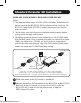
B140-1A1-WP only: Connect the external power supply to the local
unit and plug it into a Trip Lite Surge Suppressor, Power Distribution
Unit(PDU),orUninterruptablePowerSupply(UPS).TheGreen
Power LED will illuminate.
4
ConnecttheRJ45portsonthelocalandremoteunitsusing
Cat5e/6cable.
5
Connect the built-in DVI connector on the B140-101 remote unit to
the DVI monitor, or connect the B140-1A1-WP, B140-1P1-WP-1 or
B140-101X remote unit to the monitor using a Tripp Lite
P561-SeriesDVIcable.
6
B140-1A1-WP and B140-101X only: Connect the external
power supply to the remote unit and plug it into a Tripp Lite Surge
Suppressor, Power Distribution Unit (PDU) or Uninterruptible Power
Supply(UPS).TheGreenRJ45LEDontheB140-101Xremoteunit
willilluminatetoindicateitisreceivingpower.TheGreenPowerLED
will illuminate on the B140-1A1-WP remote unit.
7
TurnonthepowertotheDVIsource.TheGreenRJ45LEDswill
illuminate on the B140-101 and B140-101X units, and the Power
LEDs will illuminate on the B140-1P1-WP-1 units to indicate that
theyarereceivingpower.TheOrangeRJ45LEDwillilluminateonthe
B140-101X remote unit to indicate it is receiving a signal from the
source. The Orange Activity LEDs will illuminate on the
B140-1A1-WP units.
8
B140-1A1-WP and B140-101X only: If necessary, adjust the
Equalization control on the remote unit to improve the video image.
Note: An improper Equalization setting can cause the monitor not
to display a picture at all. Try each Equalization setting until an
acceptable image is displayed.
201110026-93-3094-EN.indd 10 11/3/2011 11:37:09 AM