Owner’s Manual HDBaseT HDMI Over Cat5/Cat6 Extenders Extender Kit Models: BHDBT-K-SI, BHDBT-K-SI-ER, BHDBT-K-SI-LR Matrix Transmitter Models: BHDBT-T-SI-4X2, BHDBT-T-SI-4X4 Transceiver Models: BHDBT-TR-SI, BHDBT-TR-SI-ER, BHDBT-TR-SI-LR Receiver Models: BHDBT-R-SI, BHDBT-R-SI-ER, BHDBT-R-SI-LR PROTECT YOUR INVESTMENT! Register your product for quicker service and ultimate peace of mind. You could also win an ISOBAR6ULTRA surge protector—a $50 value! www.tripplite.com/warranty 1111 W.
Table of Contents Package Contents 2 Product Features 3 Optional Accessories 5 Mounting Instructions 5 Installation 6 Standard Extender Kit Installation 6 Extender Kit with Transceiver Installation 8 Matrix Transmitter Installation 10 RS-232 Serial Control (Matrix Transmitter Units Only) 13 Troubleshooting 14 Warranty and Product Registration 15 Regulatory Compliance 16 BHDBT-K-SI BHDBT-K-SI-ER BHDBT-K-SI-LR BHDBT-T-SI-4X4 BHDBT-T-SI-4X2 BHDBT-TR-SI BHDBT-TR-SI-ER BHDBT-TR-SI-LR BHD
Product Features • Extends HDMI audio/video, RS-232 Serial and IR Control Signals over Cat5/6 cabling. • Supports 7.1-channel surround sound, DTS-HD and Dolby True HD audio. • Uses a 39 KHz IR frequency. • Supports RS-232 Serial full-duplex baud rates up to 3 Mbps. • EDID, HDCP and 3D compatible. • Includes mounting hardware that allows unit to be wall-mounted, rack mounted or pole mounted. • Matrix transmitter units allow multiple HDMI inputs to be connected and distributed among multiple outputs.
Compatible Models 1080p Max Distance – Cat5e / Cat6 1080p Max Distance – Cat6a 4K Max Distance – Cat5e / Cat6 Model 4K Max Distance – Cat6a Unit Type Product Features A. BHDBT-K-SI Kit 130 ft. (40 m) 115 ft. (35 m) 230 ft. (70 m) 200 ft. (60 m) F B. BHDBT-K-SI-ER Kit N/A N/A 500 ft. (150 m) 500 ft. (150 m) G C. BHDBT-K-SI-LR Kit 328 ft. (100 m) 230 ft. (70 m) 328 ft. (100 m) 328 ft. (100 m) H D.
Optional Accessories • N001-Series Cat5 Patch Cables • N022-01K-GY Cat5 24 AWG Solid Wire Bulk Cable – 1,000 ft. • N202-Series Cat6 24 AWG Solid Wire Patch Cables • N222-01K-BL Cat6 24 AWG Solid Wire Bulk Cable – 1,000 ft. • P520-006 RS232 Serial Extension Cable – 6 ft. • P568-Series High Speed HDMI Cables Mounting Instructions The HDBaseT HDMI Over Cat5 / Cat6 Extender products come with mounting hardware that allows them to be mounted in a variety of ways.
Installation Standard Extender Kit Installation Notes: 1. See the Product Features section of this manual for information on your model’s maximum supported distances and resolutions. 2. Test to make sure the entire installation works properly before pulling cables through ceilings/walls. 3. To achieve maximum distance and performance, use 24 AWG solid wire Cat5e/6 or 23 AWG solid wire Cat6a cable.
Installation 1. Make sure that the HDMI and RS-232 serial source is powered off. 2. Connect the HDMI source to the HDMI Input port on the local transmitter unit. 3. Connect the included 3.5 mm Male-to-DB9 female adapter cable to the RS-232 port on the local transmitter unit, then connect the computer to the adapter. 4. Connect the IR-IN cable to the IR-IN port on the local transmitter unit.
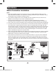
Installation Extender Kit with Transceiver Installation Notes: 1. The below installation diagram and instructions are for an HDBaseT HDMI over Cat5 Extender Kit installation, though installation will be similar if you purchase the transmitter and receiver units separately. 2. See the Product Features section of this manual for models compatible with your transceiver and for information on the maximum supported distances and resolutions for your model. 3.
Installation 4. Connect the IR-IN cable to the IR-IN port on the local transmitter unit. Note: The IR-IN unit accepts a signal from a remote control and sends it to a device controlled on the other end of the installation. Position the IR-IN unit in an unobstructed area that can easily accept a remote control signal. 5. Connect the IR-OUT cable to the IR-OUT port on the local transmitter unit.
Installation Matrix Transmitter Installation Notes: 1. The below installation diagram and instructions are for a standard HDBaseT HDMI over Cat5 Matrix Transmitter installation. For instructions on adding transceivers to your installation, refer to the Extender Kit with Transceiver Installation section. 2. The installation diagram below shows a BHDBT-T-SI-4X2. Installation will be the same for the BHDBT-T-SI-4X4, except for the number of HDMI Output ports. 3.
Installation 1. Make sure that the HDMI source and RS-232 serial source is powered off. 2. (Optional) Connect the 3.5 mm male-to-DB9 female adapter cable included with the transmitter unit to the RS-232 port on the left rear of the unit, then connect the cable to the computer that will be serially controlling the unit. 3. (Optional) Connect the IR extension cable included with the transmitter unit to the 3.5 mm jack to the right of the RS-232 serial port mentioned in step 2.
Installation 14. Connect the 3.5 mm male-to-DB9 female adapter cable included with the receiver unit to the RS-232 port on the receiver unit, then connect the RS-232 device to the adapter. 15. Connect the IR-IN cable included with the receiver unit to the IR-IN port on the remote receiver unit. Note: The IR-IN unit accepts a signal from a remote control and sends it to a device to be controlled on the other end of the installation.
RS-232 Serial Control (Matrix Transmitter Units Only) Before using RS-232 serial control, you must first access Terminal Emulation Software and update the COM port settings. 1. Go to the Setup drop-down menu and select the Serial Port option. 2. Select the COM port that is being used and update the remaining settings: Baud Rate (57600), Data (8 bit), Parity (none), Stop (1 bit), Flow Control (none). 3. Next, you will need to configure your software to allow input control.
Troubleshooting If you are unable to obtain an acceptable image after following these installation instructions, try the following troubleshooting tips: 1. Are the external power supplies that came with the product connected and plugged into a working power source? For the product to function properly, it must be connected to and receiving power from the external power supply. 2. Was the power to the connected devices turned off prior to installation? If not, restart them. 3.
Troubleshooting 7. Check your cabling for any damages that may have occurred during installation. If a cable connector is loosened from being pulled through ceilings/ walls or the cable jacket is damaged causing the wiring to be exposed, you will not be able to achieve maximum performance. 8. Are the transmitter, transceiver, and/or receiver located in an area that exposes them to higher temperatures? If the product is overheated, it will not function properly. 9.
Regulatory Compliance FCC Notice, Class B This device complies with part 15 of the FCC Rules. Operation is subject to the following two conditions: (1) This device may not cause harmful interference, and (2) this device must accept any interference received, including interference that may cause undesired operation. Note: This equipment has been tested and found to comply with the limits for a Class B digital device, pursuant to part 15 of the FCC Rules.