ce TY N chanuct! N IO a d RA ATy for e pro nty R R a it rra A W ISTe todipp L /wa r m G lin T o REer on REE lite.c F pp st gi in a .tri Re w ww to w Owner’s Manual NetCommander™ Cat5 Rackmount Console KVM Switches Models #: B070-008-19 & B070-016-19 1111 W. 35th Street, Chicago, IL 60609 USA www.tripplite.com/support Note: Follow these instructions and operating procedures to ensure correct performance and to prevent damage to this unit or to its connected devices. Copyright © 2010 Tripp Lite.
Table of Contents Features.. ......................................................................................... p. 3 Package Includes…......................................................................... p. 3 Accessories….................................................................................. p. 3 Configuration…............................................................................... p. 4 Front View................................................................................ p.
Features • 8-port or 16-port KVM switch with built-in 19" LCD display, keyboard and touch pad • Access and control multiple multi-platform computers from a single console • Hot-swappable: disconnect and reconnect USB computers without rebooting • Auto-scan: with variable time interval • Compact design: 1U rack mountable • Easy port selection using (1) On Screen Display (OSD), (2) keyboard hotkeys key sequences • Expandable: control up to 256 computers by adding additional KVM switches • Simple cable managem
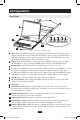
Configuration Front View 6 10 7 12 1 2 3 4 5 8 Figure 2 NetCommander KVM Buttons 13 11 9 Figure 1 NetCommander KVM front panel 1 Auto: When the LCD Menu is closed, pressing the AUTO button will perform an Auto Adjust on the monitor screen. When the LCD Menu is open, pressing the AUTO button will bring you back to the previous screen/selection. If the LCD Menu cannot go back any further, the AUTO button will close down the menu.
Configuration (continued) Rear View 1 2 3 5 4 6 Figure 3 NetCommander KVM rear panel 1 Power Socket: The power cord plugs in here from the AC power source. 2 On/Off Switch: Turns the KVM Switch on and off. 3 Firmware Upgrade Port: Plug included firmware upgrade cable into this port to download firmware upgrade data. 4 CPU Port Section: Plug the Cat5e cables from each PC or server into these ports.
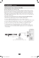
Installation (continued) NetCommander Server Interface Unit (SIU) The NetCommander Server Interface Unit The Server Interface Unit gets its power from the connected computer. In the case of the NetCommander PS/2 Server Interface Unit (B078-101-PS2), the power is drawn from the keyboard port. In the case of the NetCommander USB Server Interface Unit (B078-101USB), the power is drawn from the USB port. When connected and receiving power, the green LED on the SIU will illuminate.
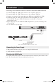
Installation (continued) Connecting a NetCommander USB Server Interface Unit (Model # B078-101-USB) 1. Connect the B078-101-USB VGA connector to the computers VGA port 2. Connect the B078-101-USB USB connector to the computers USB port 3. Connect one end of the Cat5 patch cable to the RJ45 port on the B078-101-USB* 4. Connect the other end of the Cat5 patch cable to the desired RJ45 port on the Console KVM.* The green LED will illuminate when the SIU is connected and receiving power. 5.
Installation (continued) Rackmount Considerations Ambient Operating Temperature The ambient operating temperature in the rack may be an issue and is dependent upon the rack load and ventilation. When installing in a closed or multi-unit rack assembly, make sure that the temperature will not exceed the maximum rated ambient temperature. (32º to 104º F) Airflow Ensure that the airflow within the rack is not compromised.
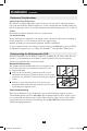
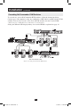
Installation (continued) Cascading NetCommander KVM Switches To cascade two or more NetCommander KVM switches, follow the instructions below. Connect up to 256 computers* using any combination of B072-008-1 and B072-016-1 KVM switches. You can only cascade 1 extra level of KVM switches onto the Console KVM. * When all 16 ports of a B070-016-19 have a B072-016-1 cascaded from them. Setting the different OSD display hotkeys for cascaded KVMs is explained on page 14.
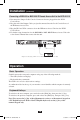
Installation (continued) Connecting a B050-000 or B051-000 IP Remote Access Unit to the B070-016-19 1. Disconnect the Jumper Cable Console Connectors that are plugged into the KVM Console Ports. 2. Plug the end of the Jumper Cable you just disconnected into the Local Console Ports of the IP Remote Access Unit. 3. Plug the PS/2 and VGA connectors from the IP Remote Access Unit into the KVM Console Ports. 4.
Operation (continued) On-Screen Display To invoke the OSD: Press and release the Shift key twice to open the OSD Main Menu. Lines with Blue text represent ports that have a computer/server connected to them, which is currently turned on. Lines with Gray text represent ports that either has a computer/server connected to them, which is turned off; or they have no computer/server connected at all.
Operation (continued) General Settings With the highlight line on the word GENERAL, press [Enter]. The General Settings window appears (see Figure 10). Security Figure 10 The General Settings window The Security option in the OSD General Settings Menu allows you to activate or deactivate Password Security. By default, Password Security is set to Off. Only the Administrator will be able to activate/deactivate Password Security. To activate/deactivate Password Security: 1.
Operation (continued) When you have cascaded KVM switches, a lower level Switch must have a different OSD display hotkey than a higher level switch. To change the top-level switch hotkey: 1. Highlight the Hotkey option in the OSD General Settings Menu 2. Press the space bar to toggle through the various options 3. When you've selected the desired hotkey, simply exit the OSD. Hitting the Enter key is not required to activate your selection To change a lower level hotkey: 1.
Operation (continued) Editing the Switch Name The KVM Switch Name appears at the bottom of the OSD General Settings Menu, and can be changed to whatever you want. When cascading, it is necessary to access the cascaded KVMs OSD using it's own hotkey. Giving cascaded KVMs OSDs unique names makes it easier when accessing them to verify which switches OSD you are accessing. To change this name simply type over the existing letters.
Operation (continued) To add/change a hotkey: 1. Highlight the desired port and press the Tab key until the HKEY column is highlighted 2. Press the space bar to toggle through the various choices 3. When you've selected the desired hotkey, simply exit the OSD. Hitting the Enter key is not required to activate your selection Time Settings In the Settings window navigate to the Time line and press [Enter]. The Time settings window appears (see Figure 12).
Operation (continued) Security Figure 13 The Security settings window The OSD offers an advanced password security system made up of three different security levels, each having its own access rights. Administrator (Status A): The Administrator has access to all features of the KVM, allowing them to Set/Modify all Passwords and Security Profiles, gain full access to any computer connected to the KVM and usage of all OSD features.
Operation (continued) User Settings 1. Highlight the Users option in the OSD Settings Menu and hit the Enter key. 2. The Users will be represented in the 6 columns on the right side of the screen. To change the access for a given computer, highlight the desired computer and hit the Tab key until the desired user is highlighted. 3. Press the space bar to toggle between the 3 access options (Y, V or N). See page 16 for details on these 3 options.
Operation (continued) Tuning (F5) You can tune the image of any remote computer screen. To adjust the screen image: 1. In the OSD Main Menu highlight the computer you want to adjust. 2. Press the [F5] key. The screen image of the selected computer is displayed, along with the Image Tuning label. 3. Adjust the image by using the Right and Left Arrow keys. 4. When the image is satisfactory, press [Esc]. Note! Distance affects picture quality.
Firmware Upgrade (continued) 3. On the upgrade computer (the computer connected to the KVM via the firmware upgrade cable), go to the Tripp Lite website and download the NetCommander Firmware Upgrade Utility .exe file, Firmware Upgrade .tfp file and Firmware Upgrade information doc. Note: The firmware upgrade information document will list the latest firmware for all Tripp Lite NetCommander KVM switches and SIUs, which you will need to reference when determining if your device has the latest firmware.
Firmware Upgrade (continued) 1. Check the firmware versions of the KVM (Switch Manager), KVM OSD (Switch OSD) and SIUs by clicking on the boxes next to them and pressing the F/W Version button. Note: To select a device, you must first unselect any boxes that have already been checked. To select or unselect all SIUs at once, simply click on the Select All or Unselect All button at the bottom of the upgrade utility. 2.
Firmware Upgrade (continued) 7. Towards the end of the firmware upgrade, a prompt will appear asking you if you want to set the OSD to its default settings. If yes, click the Yes button. If no, click the No button. The upgrade will continue. 8. Upon completion, the new firmware version will be displayed next to the upgraded unit in the upgrade utility, and the KVM screen will no longer be blacked out.
Troubleshooting Note: Disconnect device from AC mains before service operation! When using Firmware Update software you may at times get a Communication Error message. If a Communication Error message does appear during the update procedure, do the following: 1. Ensure that the RS232 Serial cable's RS232 connector is connected to the Switch's Communication port. 2. Ensure that the RS232 Serial cable's DB9F connector is connected to the DB9M Serial port on the CPU's rear panel. 3.
USB/SUN Combo Keys The connected PS/2 keyboard does not have a special SUN keypad to perform special functions in the SUN Operating System environment. When a B078-101-USB (SIU) is connected to a SUN computer, the SIU emulates these SUN keys using a set of key combinations called Combo Keys. See the table below.
FCC Radio/TV Interference Notice Note: This equipment has been tested and found to comply with the limits for a Class A digital device, pursuant to Part 15 of the FCC Rules. These limits are designed to provide reasonable protection against harmful interference when the equipment is operated in a commercial environment.