W pr ch reg RE A od an is G R uc ce te IS R t— to r o T A ww w nlin RA NT w. in a e t T Y tri F od IO pp R a N lit EE y fo : e. T r co rip a m p /w Li ar te ra nt y User’s Guide SNMPWEBCARD Firmware Version 12.06.0062 through 12.06.0065 Revision A Table of Contents 1. Introduction 1.1 System Requirements 2 2 2. Installation and Configuration 2 2.1 Saving Configuration Changes 2 2.2 Default UPS System Shutdown Settings 2 2.3 Other Default Settings 3 2.4 SNMP Configuration 3 3.
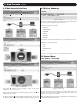
1. Introduction SNMPWEBCARD is an optional network card that you can install in the accessory slot of a compatible UPS system, PDU* or cooling unit. SNMPWEBCARD connects your Tripp Lite device to your Ethernet network as a manageable device that supports remote monitoring, remote control and remote condition reporting. You can manage the device from PowerAlert Network Management System, an SNMP Network Management Station, a Web browser or telnet.
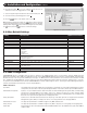
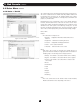
2. Installation and Configuration continued 6. Click the Action field F to access its submenu. Select the device to shut down in the Select Trigger Device section G . 7. Set how long the delay should be before the action will take place H . 8. Select the Event(s) that will trigger the action I . 9. Click the button on the bottom of the screen J . G Note: Whenever changes are made, the button must be pressed to submit the changes before moving off of the page.
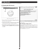
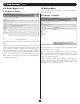
3. Web Console The Web console is the primary graphical user interface for the SNMPWEBCARD. 3.1 Opening the Web Console The application screen includes a communication status message A that indicates the progress of the application in finding a device, making a connection and completing the login attempt successfully. A Figure 3-1: Web Console Login 1. Open a Web browser that supports frames, forms and Java. PowerAlert versions 12.06.0061+ are compatible with Java 1.7. Older versions may require Java 1.
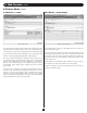
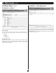
3. Web Console continued 3.2 Web Console Interface 3.3 Device Summary B C D Figure 3-4: Devices The Device Summary displays the current Alarm Status, Model Name, Device Type and user-defined location of a device. Valid Alarm Status values include: • NORMAL • INFORMATION • WARNING • STATUS • CRITICAL • OFFLINE Model Name is detected automatically and is not editable by the user. Valid Device Type values include • UPS • PDU • ENVIROSENSE • AC Location is user-defined.
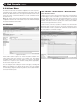
3. Web Console 3.4 Status Menu continued continued 3.4.2 Status > Details The content of this screen will vary based upon the protocol of the device. This screen contains the device variable data. Any editable variables will be displayed at the top of the list. The editable variables have a white value box. This section of variables is sorted by purpose and within each purpose, by variable name.
3. Web Console 3.4 Status Menu continued 3.5 Device Menu continued 3.4.3 Status > Alarms The device menu is used to enact different commands or configurations for individual devices. 3.5.1 Device > Controls Figure 3-8: Alarms This submenu provides a listing of all active and/or unacknowledged alarms. Figure 3-9: Controls By default, only active alarms will be displayed on this page, as the software will automatically mark the alarm acknowledged upon receipt of the matching clear alarm.
3. Web Console 3.5 Device Menu continued continued 3.5.2 Device > Loads 3.5.3 Device > Load Groups Figure 3-10: Loads Figure 3-11: Load Groups The Loads menu option will only appear if the device supports loads. The description field is an editable value. In order to save any changes made on this page, you must click the [Save] button at the bottom of the page. The Load Groups menu option will only appear if the device has two (2) or more controllable loads.
3. Web Console 3.5 Device Menu continued 3.5.5 Device > Device Discovery continued 3.5.4 Device > Events Figure 3-13: Device Discovery Figure 3-12: Events To search for additional devices, click [Execute] at the bottom of the page. This feature can be used when adding a Tripp Lite ENVIROSENSE temperature and humidity probe. Once the probe is connected to the SNMPWEBCARD, press the [Execute] button and the probe will appear as a device in the device list.
3. Web Console continued 3.6 Actions Menu The Actions menu allows for detailed configuration of event responses, scheduled actions, and the contact information in the address book. At this time, the Web interface does not support scheduled actions. Please refer to the Telnet or SSH menu interface to create scheduled actions (Section 4.2.2.2). Note: The Actions menu in the Web interface was formerly called the Configuration menu.
3. Web Console 3.6 Actions Menu continued continued 3.6.1.1 Actions > Event Actions > Device Actions continued Device Shutdown Actions Device shutdown actions allow you to shutdown a device when a user-defined trigger occurs. Triggers include various alarms and even ENVIROSENSE readings. Device shutdown also includes the option to be put on a delay. To add an action, click the [+] button to activate a row and enter the appropriate data.
3. Web Console 3.6 Actions Menu continued continued 3.6.1.1 Actions > Event Actions > Device Actions continued Ramp Actions A ramp action is a device specific action that can be executed when an alarm trigger occurs. An example of a ramp action could be that when a UPS returns from an on battery event, the event trigger would be ‘On Utility Power,’ to execute the ramp settings set on the controllable loads. Ramp settings are defined on the Device-Loads page.
3. Web Console 3.6 Actions Menu continued continued 3.6.1.2 Actions > Event Actions > General Actions Email Actions An Email action is an action that will send emails to selected people in the address book when user-defined events are detected. It is possible to define multiple email actions so that different people are notified when different alarms are detected or different people are notified if the triggering event lasts longer than expected.
3. Web Console 3.6 Actions Menu continued continued 3.6.1.2 Actions > Event Actions > General Actions 3.6.2 Actions > Scheduling continued SNMP Trap Actions An SNMP Trap action is an action that will send SNMPv1 traps to selected destinations in the address book when selected events are detected.
3. Web Console continued 3.6.3 Actions > Address Book 3.7.1 Logs > Event Logs Figure 3-25: Address Book Figure 3-26: Event Logs To modify Address Book settings for each type of notification method, locate it in the ‘Contacts’ box on the left side of the page and edit the variable fields. This menu allows the user to view the event log entries for the entire system. The “Email” tab shows a table of email contacts.
3. Web Console 3.7.2 Logs > Data continued continued Data points are listed in order of the time and date they occurred. Information on the type of data point that occurred, the device it occurred on, which variable it occurred on and the numeric value is also displayed. To view more data points, simply continue scrolling down through the log. Logs can be filtered by using the menus at the bottom of the page.
3. Web Console 3.8 Preferences continued continued 3.8.1 Preferences > Network continued SMTP The email settings are used to define a remote email relay server to use to send emails from the system. These settings also indicate what items to include in email notifications. From Address This is the address that the email will be sent from. The default is poweralert@tripplite.com. Subject This is the information to be used as the “Subject” line in the message. The default is “PowerAlert Notification”.
3. Web Console 3.8 Preferences continued continued 3.8.1 Preferences > Network continued Internet This menu can be used to monitor and alter IPv4 and IPv6 settings such as the addresses in use and the settings on system restart. Changes made in this menu will require a system reboot. DNS Settings In Use This list shows the DNS servers currently used by SNMPWEBCARD. DNS Settings Enter the IP address of the DNS server that will be providing lookup services for SNMPWEBCARD.
3. Web Console 3.8 Preferences continued continued 3.8.3 Preferences > Security continued Users This menu allows for the definition and management of various users allowed to access various aspects of the network. There are a total of 12 available user slots. User Definition Menu Data The following is the data that is used to define the local users. Not all data applies to all user types and will be identified accordingly.
3. Web Console 3.8 Preferences continued continued 3.8.3 Preferences > Security continued Logging- This facility allows access to logs and log rotation actions. Log rotation actions will only be available if the user has at least Read Only access to the Contacts facility. Device Status- The facility provides access to all device variable information. These would include device status variables, personalization variables and threshold variables.
3. Web Console 3.8 Preferences continued continued 3.8.3 Preferences > Security continued ACL IP Mask (Users with SNMP Access Only) This defines the Subnet Mask to use with the ACL IP Address to determine if an address is one from which the user is allowed to access the data via SNMP. • RADIUS Then Local The system uses RADIUS for authentication first, if not authorized via the RADIUS server, the locally defined users will be used for authentication. 192.168.1.1 (single) 255.255.255.255 192.168.1.
3. Web Console 3.8 Preferences continued continued 3.8.4 Preferences > System This menu allows you to view and modify preferences throughout the system, including: Data Logging Accounting Logging Event Logging Figure 3-38: Data Logging Figure 3-36: Accounting Logging Application Logging Figure 3-39: Event Logging Figure 3-37: Application Logging The Accounting, Data and Event log settings allow you to define the number of records to be stored and persisted across a reboot of the SNMPWEBCARD.
3. Web Console 3.8 Preferences continued continued 3.8.4 Preferences > System continued The SNMPWEBCARD supports a date and time configuration via Simple Network Time Protocol (SNTP) or the on-board Real-Time Clock (RTC). Both the SNTP and RTC time are able to utilize the local time configuration. Refer to Section 4.2.4.2 Time Settings for additional details on local time configuration. Remote Syslog Changes on the Date and Time menus require a restart to take effect.
3. Web Console 3.8 Preferences continued continued 3.8.4 Preferences > System continued Miscellaneous • Erase the user configuration and system log database • Reset the Root password back to TrippLite Reset Users Reset the default user settings, including clearing any RADIUS settings.
3. Web Console continued 3.
4. Telnet/SSH Console Most of the monitoring and control features available in the Web console (see Section 3 – Web Console) are also available in the telnet and/or SSH console. Accessing the SNMPWEBCARD through the telnet console is ideal for mobile or resource-limited platforms. Configuring Energywise If you intend to use the SNMPWEBCARD’s Energywise facility, refer to the Energywise instruction manual for details on how to configure this interface.
4. Telnet/SSH Console continued Menus Main Menu The main menu is the starting menu when a user accesses the Telnet interface. It contains the entry point for all of the pieces of the system data. All other menus are accessible from the main menu. To help keep the user informed about active alarms, the current list of active alarms is always displayed as part of the main menu. Tripp Lite (c) Copyright 2005-2012 PowerAlert 12.06.
4. Telnet/SSH Console continued 4.1 Device Menu continued 4.1.1 Status This menu displays the status variables for the device. The values in this menu are not editable. The exact data shown on this menu will be device dependent.
4. Telnet/SSH Console continued 4.1 Device Menu continued 4.1.2 Identification This is the section of the device menus that will contain the information about the device. This information will be both user-defined settings such as device name or location and equipment specific information like vendor, product and protocol. There are data items on this menu which will be displayed for all devices and some data displayed based upon the type and protocol for the device.
4. Telnet/SSH Console continued 4.1 Device Menu continued 4.1.2 Identification continued Port Mode This is the connection mode of this device. The valid values are: • RS232 • USB • HID Port Name Name of the port this device is on. 4.1.3 Controls This section of the menu is used to present the controls that are available for the device. When a control is chosen and it does not have any control data associated, the user will be prompted for verification that they really wish to execute the control.
4. Telnet/SSH Console continued 4.1 Device Menu continued 4.1.3.1 Control Data This menu displays the list of data items associated with the control. The options from this menu are to choose the number associated with the data item or to execute (“E”) the control. If “E” is chosen, the user will be prompted to verify that they wish to execute the control. If verified, the control is executed. If they choose one of the data items, they will be prompted to enter the new value.
4. Telnet/SSH Console continued 4.1 Device Menu continued 4.1.4 Events Events To access the events menu, the user must have at least Read access to the DEVICE EVENTS, ACTIONS and CONTACTS facilities in addition to the DEVICE STATUS facility.
4. Telnet/SSH Console continued 4.1 Device Menu continued 4.1.4 Events Menu Data Event Category This specifies the severity level for the event. The user may choose to give different events different severity levels. The valid values for category are: • CRITICAL • WARNING • INFORMATION Enable/Disable Event This allows the user to no longer consider the event an alarm event. Disabling it causes the event to no longer create an alarm, and the assigned actions will no longer fire when this event occurs.
4. Telnet/SSH Console continued 4.1 Device Menu continued 4.1.4 Events Menu Data Event This is the label of the event to which actions will be assigned. This is a display only value. Event Clear This is the clear label of the event to which the actions are being assigned. This is a display only value. Event Action This is also called the set action. It is the action to be taken when this event occurs. Event Clear Action This is the action to be taken when this event clears.
4. Telnet/SSH Console continued 4.1 Device Menu continued 4.1.5 Loads To access the load menus, the user must have at least Read access to the DEVICE LOADS and DEVICE STATUS facilities. Additionally, a user may be able to update Loads options by accessing outlet realms. You can control the outlets of a managed device by selecting the load plugged into it and clicking the desired [On], [Off] or [Cycle] control. Each load bank consists of one or more outlets.
4. Telnet/SSH Console continued 4.1 Device Menu continued 4.1.5.2 Load Groups The Load Groups menu is not available for all devices. Devices that support loads groups must have 2 or more loads and provide a mechanism for updating multiple loads with a single command. If the device does not support load groups, then this menu will not be available.
4. Telnet/SSH Console continued 4.1 Device Menu continued 4.1.5.3 Ramp/Shed Settings This menu allows the user to modify the ramp and shed settings for the entire device in one operation. This is to ensure that the user can make all of the changes necessary before a ramp/shed synchronization is started. The menu will prompt the user to make sure that all of the changes have been made before saving.
4. Telnet/SSH Console continued 4.1 Device Menu continued 4.1.5.3 Ramp/Shed Settings continued Menu Data Ramp Action This is the action to take when a ramp is initiated. The valid values are: Shed Action This is the action to take when a shed is initiated. The valid values are: • Remain Off • Remain On • Turn On After Delay • Turn Off After Delay Ramp Delay This is the delay before taking the ramp action. Shed Delay This is the delay before taking the shed action. 4.1.
4. Telnet/SSH Console continued 4.1 Device Menu continued 4.1.7 Device Alarms This view is similar to the alarm view except the alarms displayed here are for the selected device only. The option to allow or disallow auto acknowledge alarms is not available at the device level. It must be done system wide from the system alarms menu. 4.1.8 Logs Display the logs that apply to the selected device only.
4. Telnet/SSH Console continued 4.2 System Configuration continued 4.2.1.1 Email Contacts This section of the menus is used to define the email contacts. Summary Menu -------- Email Contacts ------------------------------------------------------------# Name Email Address 1 John John@mail.com 2 Nancy Nancy@mail.
4. Telnet/SSH Console continued 4.2 System Configuration continued 4.2.1.2 SNMP Contacts The destinations defined that can be used to send SNMP traps or perform SNMP set OID operations. SNMP Contacts Summary Menu -------- SNMP Contacts Menu ---------------------------------------------------# Name Host Address Port Version 1 mycommunity 10.10.10.10 200 SNMPV1 2 snmpv3 destination 10.11.12.
4. Telnet/SSH Console continued 4.2 System Configuration continued 4.2.1.2 SNMP Contacts continued Menu Data SNMP Version This defines a valid SNMP Version supported on the SNMP destination. The valid values are SNMPV1, SNMPV2c, and SNMPV3. This setting will determine which of the other values that need to be entered. Community (SNMPV1 and SNMPV2c only) For SNMPv1 or SNMPv2 recipients, this must be a valid community for the receiving agent.
4. Telnet/SSH Console continued 4.2 System Configuration continued 4.2.1.3 HTTP Contacts continued Menu Data Name The name is the character string which contains a unique identifying name for the HTTP destination. Authentication Login Name This is an optional login name used for authentication. The string must have a length between 8 and 32 characters. Protocol Choose “http” for non-secured HTTP and “https” for secured HTTP.
4. Telnet/SSH Console continued 4.2 System Configuration continued 4.2.2.1.
4. Telnet/SSH Console continued 4.2 System Configuration continued 4.2.2.1.1 Email Notification Action Menus continued Menu Data Email Contacts Chosen The email notification action requires the user to define a list of contacts that will receive email notification when an event occurs. When the option is set to ALL, every email contact in the system will receive the notification and any new users added will automatically be included in the list without any further changes to the action.
4. Telnet/SSH Console continued 4.2 System Configuration continued 4.2.2.1.
4. Telnet/SSH Console continued 4.2 System Configuration continued 4.2.2.1.3 SNMP Set OID Action Menus SNMP Set OID actions will make an SNMP Set request to a list of SNMP Contact Destinations.
4. Telnet/SSH Console continued 4.2 System Configuration continued 4.2.2.1.4 Device Specific Menus The device specific menus are actions that occur on a specific device. They may be applied to any device event. Common Data Device ID Since all of these actions will occur on a specific device, they require the user to specify the device.
4. Telnet/SSH Console continued 4.2 System Configuration continued 4.2.2.1.
4. Telnet/SSH Console continued 4.2 System Configuration continued 4.2.2.1.4 Device Specific Menus continued Detail Menu -------- Device 1 Ramp Action Profile Detail ----------------------------------Name: ramp device loads Delay: 0 Device: 1 1- Modify Profile Name 2- Modify Delay A- Apply Changes D- Delete X- Device Ramp Action Profiles Menu M- Return to Main Menu Refresh Menu Shed Action Menus Summary Menu Only one device available for this action type. Using device 1.
4. Telnet/SSH Console continued 4.2 System Configuration continued 4.2.2.1.4 Device Specific Menus continued Control Execution Action Menus Summary Menu Only one device available for this action type. Using device 1.
4. Telnet/SSH Console continued 4.2 System Configuration continued 4.2.2.1.4 Device Specific Menus continued Menu Data Control This is the control to be executed by the action. Control Data Some controls have additional data. For those controls, the data settings may be changed. 4.2.2.1.5 Applying Actions to Events Choosing this option begins the process of assigning the action to events. Each event has both a “Set” and a “Clear” action associated with it.
4. Telnet/SSH Console continued 4.2 System Configuration continued 4.2.2.1.5 Applying Actions to Events continued Menu Data Using Action for Set Action The action will be used for the “Set” action only. The user will be given the option to choose the “Clear” action before continuing on to select events. Using Action for Both Set and Clear Action The action will be used for both “Set” and “Clear” and the user can immediately continue on to choose events.
4. Telnet/SSH Console continued 4.2 System Configuration continued 4.2.2.1.5 Applying Actions to Events continued Menu Data Apply To All Events This option will apply the “Set” and “Clear” actions chosen to all of the events on the selected devices. If the “Set” and “Clear” actions are already assigned but are not paired with the same “Set” and “Clear” action, the user will be prompted to leave those assignments alone or to clear those assignments and assign the chosen actions in their place.
4. Telnet/SSH Console continued 4.2 System Configuration continued 4.2.2.2 Schedules To have access to the schedules menu, the user must have at least Read access to the SCHEDULES facility. Because controls and loads can be scheduled, the user should have at least read access to the DEVICE CONTROLS and DEVICE LOADS facilities as well. Once a schedule has been created, it cannot be modified. To change a schedule, the original schedule has to be removed and a new schedule created.
4. Telnet/SSH Console continued 4.2 System Configuration continued 4.2.2.
4. Telnet/SSH Console continued 4.2 System Configuration continued 4.2.2.
4. Telnet/SSH Console continued 4.2 System Configuration continued 4.2.2.2 Schedules continued Menu Data Device ID This field selects the device to which the schedule is to be applied. Relative Days This setting is used for monthly and yearly schedules. It allows a relative day of a month to be specified. The valid relative day selection are: Pending Action This field indicates the action to be fired according to the schedule.
4. Telnet/SSH Console continued 4.2 System Configuration continued 4.2.3 Security Security Menu -------- Security Menu --------------------------------------------------------1- Authentication Method 2- Local Users 3- Radius Servers 4- Change Password X/M- Return to Main Menu Refresh Menu 4.2.3.
4. Telnet/SSH Console continued 4.2 System Configuration continued 4.2.3.2 Local Users This menu is used to define the local users. Local users include SNMP v3 users and SNMP v1/v2c communities which must be defined locally. RADIUS authentication may not be used for SNMP access. There are a total of 12 users that may be defined with 5 default users being created initially. Available slots will be identified in the user summary table with the name/community of “User Not Defined.
4. Telnet/SSH Console continued 4.2 System Configuration continued 4.2.3.2 Local Users continued Logging This facility allows access to logs and log rotation actions. Log rotation actions will only be available if the user has at least Read Only access to the Contacts facility. Device Status The facility provides access to all device variable information. These would include device status variables, personalization variables and threshold variables.
4. Telnet/SSH Console continued 4.2 System Configuration continued 4.2.3.
4. Telnet/SSH Console continued 4.2 System Configuration continued 4.2.3.2 Local Users continued Menu Data Localadmin This is the administrator account and has Read/Write access to all program areas. This user cannot be deleted or its facility access permission be modified, but the username and password may be changed from its default settings. The default password is same as the username. Localmanager This account has default access as Read/Write to all areas except to the security area of the program.
4. Telnet/SSH Console continued 4.2 System Configuration continued 4.2.3.3 RADIUS Servers continued Menu Data Address This defines the internet address of the RADIUS server. Authentication Port This defines the port on the server to be used for authentication. Priority This is a number that defines the priority of this RADIUS server. Accounting Port This defines the port on the server to be used for accounting. Shared Secret This is the shared secret value to be used with this RADIUS server. 4.2.3.
4. Telnet/SSH Console continued 4.2 System Configuration continued 4.2.4.2 Time Settings This menu allows the user to enter specific settings on how time is to be handled by the system.
4. Telnet/SSH Console continued 4.2 System Configuration continued 4.2.4.3 SNTP Settings This menu allows the user to control the various aspects of using NTP for setting the time and date. -------- SNTP Settings --------------------------------------------------------Update Interval : 360 Primary Address : 0.pool.ntp.org Primary Port : 125 Secondary Address : 1.pool.ntp.
4. Telnet/SSH Console continued 4.2 System Configuration continued 4.2.5 Local Device Discovery This menu is used to tell the system to attempt to discover any new device connections. To be able to effectively use this menu, the user should have Write access to the SYSTEM SETTINGS facility.
4. Telnet/SSH Console continued 4.2 System Configuration continued 4.2.6 Restart PowerAlert The restart menu provides the end user with an interface to restart the SNMPWEBCARD. If there has been a setting in the data that requires a system restart, the message “Changes have been made to require a restart to take effect” will be displayed on this menu. This message can only be cleared with a restart. Changing setting back to the original value cannot reset this condition.
4. Telnet/SSH Console continued 4.3 Network Configuration The Network Configuration menu is used to configure the network-related items such as the IP Configuration of IPV4 and IPV6 Addresses, Remote Services such as Email Settings and the User Access Information, which defines what user service should be run (HTTP, SSH or Telnet). All changes to the Network Configuration will be enacted upon the next restart of the web card.
4. Telnet/SSH Console continued 4.3 Network Configuration continued 4.3.1.1 Host Name This is a character string up to 63 characters to be used as the host name for the SNMPWEBCARD. -------- Host Name ------------------------------------------------------------Current Host Name = poweralert_0641576753151 Enter a string between 1 and 63 characters for Host Name X- Leave value unchanged M- Return to Main Menu 4.3.1.
4. Telnet/SSH Console continued 4.3 Network Configuration continued 4.3.1.4 IPV6 Settings This menu displays current IPV6 settings and allows a user to toggle the dynamic host configuration protocol and method. There can be up to six IPV6 addresses for the card. Only two of these are impacted by this menu. A user may choose to have one IPV6 Address determined through DHCP and one set statically. Any others that appear in the list have been automatically assigned by the card’s software.
4. Telnet/SSH Console continued 4.3 Network Configuration continued 4.3.1.5 DNS Settings This menu allows the user to define only one DNS server, though there may be up to two DNS servers on the system. If DHCP is used for either the IPV4 or IPV6 address, a DNS server will be defined by DHCP. The user-defined DNS server will always be in the list.
4. Telnet/SSH Console continued 4.3 Network Configuration continued 4.3.2 Remote Services This menu provides access to the configuration of the Remote Services provided by the SNMPWEBCARD including distributing notification emails and logs. -------- Remote Services ------------------------------------------------------1- Email Settings 2- Syslog Settings 3- Watchdog Settings X- Network Configuration M- Return to Main Menu Refresh Menu 4.3.2.
4. Telnet/SSH Console continued 4.3 Network Configuration continued 4.3.2.1 Email Settings continued Menu Data Server Name This defines the email server address information used for sending out email messages. Include Triggering Event This is a flag to indicate if information about the triggering event should be included in the email message if it is available. Values are: • Yes Include the data in the email message. Port This defines the port on the email server used for sending out email messages.
4. Telnet/SSH Console continued 4.3 Network Configuration continued 4.3.2.2 Remote Syslog These settings are used to define the remote syslog servers to send log entries. There are a maxmimum of 4 remote syslog servers that can be defined. To enforce this maximum, there are 4 predefined slots for the servers. An available slot will have a blank Host value and default values for Port, Log Level and Facility. Once all of those slots are used, no more may be defined.
4. Telnet/SSH Console continued 4.3 Network Configuration continued 4.3.2.2 Remote Syslog continued Menu Data Host Host Name or IP address for the Remote Syslog server. Facility The logging facility values are the Syslog facilities as defined in RFC 5424. Port This defines the port for the Remote Syslog server. The default is 514.
4. Telnet/SSH Console continued 4.3 Network Configuration continued 4.3.2.
4. Telnet/SSH Console continued 4.3 Network Configuration continued 4.3.2.3 Watchdog Settings The values in this menu are optional Watchdog settings that can be defined to verify the availability and accessibility of the network.
4. Telnet/SSH Console continued 4.3 Network Configuration continued 4.3.3 User Interfaces These menus control how the various available SNMPWEBCARD interfaces are started. 4.3.3.1 Telnet/SSH 4.3.3.2 Web Console This menu provides configuration access to the way the user and system interact with the Telnet/SSH interface. Menu Data Menu Data Automatically Start SSH Menu This menu asks if when the card is started, should the SSH Menu application be automatically started as well.
4. Telnet/SSH Console continued 4.3 Network Configuration continued 4.3.3.3 SNMP Settings 4.3.3.4 FTP This menu allows the user to configure SNMP set and get settings. This menu allows the user to configure the FTP client settings. Menu Data Menu Data Automatically Start SNMP This menu asks if when the card is started, the SNMP application should be started as well. Valid Values: Automatically Start FTP This menu asks if when the card is started, the FTP application should be started as well.
4. Telnet/SSH Console continued 4.4 Alarms and Logging This menu allows for in-depth viewing, configuration and acknowledgement of logs and alarms that come across the system. Alarms and Logging -------- Alarms and Logging ---------------------------------------------------1- Alarms 2- View Logs 3- Logging Settings X/M- Return to Main Menu Refresh Menu 4.4.1 Alarms This menu provides a summary of all alarm conditions, where they have occurred and whether they have been acknowledged.
4. Telnet/SSH Console continued 4.4 Alarms and Logging continued 4.4.1.1 Alarm Details The detail for each alarm can be displayed by choosing its ID. Once it is displayed the user has the option to acknowledge that alarm only. Active This indicates if the alarm condition is still present Alarm ID This is a number that uniquely identifies the alarm. Time This is the time that the alarm event occurred. Device ID This is the numeric device ID with the alarm condition.
4. Telnet/SSH Console continued 4.4 Alarms and Logging continued 4.4.2.1 Data Log View the data logs for the system. The data log will log only variables marked in the system to be logged.
4. Telnet/SSH Console continued 4.4 Alarms and Logging continued 4.4.2.
4. Telnet/SSH Console continued 4.4 Alarms and Logging continued 4.4.2.2 Event Log This menu allows the user to view the event log entries for the entire system. -------- Event Log ------------------------------------------------------------Order : Descending Category : All Time Range : Display All Entries V- Start Viewing Log O- Change Viewing Options C- Clear Log X- Logs Menu M- Return to Main Menu Refresh Menu >> Start Viewing Log Choosing this option will begin the data log display.
4. Telnet/SSH Console continued 4.4 Alarms and Logging continued 4.4.2.2 Event Log continued Change Viewing Options Changing the viewing options will allow the user to decide the order to view the log as well as define filters to limit that logs to be viewed. These options are active only for the single instance of viewing the log and are not persisted.
4. Telnet/SSH Console continued 4.4 Alarms and Logging continued 4.4.2.
4. Telnet/SSH Console continued 4.4 Alarms and Logging continued 4.4.3 Logging Settings This section defines the preference settings for the various types of logs. These setting include things like maximum log file sizes, logging severity levels and actions to take when the log is rotated.
4. Telnet/SSH Console continued 4.4 Alarms and Logging continued 4.4.3.3 Data Log Settings The data log settings are used to define the maximum data log size and actions to take when the log is rotated.
4. Telnet/SSH Console continued 4.4 Alarms and Logging continued 4.4.3.3 Data Log Settings continued Menu Data Protocol This defines the protocol to use when sending the data log file. The valid values are: • smtp – email to destination • http – use http or https to send to destination Destination This field is used to select the destination for the data log file. When the protocol is SMTP, the destination will be an email contact. When the protocol is HTTP, the destination will be an HTTP contact.
4. Telnet/SSH Console continued 4.4 Alarms and Logging continued 4.4.3.4 Event Log Settings continued Menu Data Protocol This defines the protocol to use when sending the event log file. The valid values are: • smtp – email to destination • http – use http or https to send to destination Destination This field is used to select the destination for the data log file. When the protocol is SMTP, the destination will be an email contact. When the protocol is HTTP, the destination will be an HTTP contact.
4. Telnet/SSH Console continued 4.5 About This menu contains information about PowerAlert. The data on this menu is read-only. The data on this menu is: -------- About PowerAlert -----------------------------------------------------OS Agent Type MAC Address Card Serial Number Driver Version Engine Version Driver File Status : : : : : : : NetOS 7.5.2tl flash: 16777216B sdram: 33554432B processor: NS9210B-0-I75 NETOS7 00:06:67:22:7D:D2 9936AY0AC732600001 12.06.0062.0999.0999 12.06.0062.0999.
5. Command Line Interface The SNMPWEBCARD 12.06.006X firmware adds support for new features on the command line interface (CLI). Many of the functional controls available in the Web console and Telnet interface are now available on the command line interface. The CLI allows for the use of user-created scripts and easier integration with third party systems. The CLI can be accessed on the SNMPWEBCARD via the management serial port, via SSH on the default port 2112, and via Telnet on the default port 5214.
5. Command Line Interface continued 5.2 Manual Pages Each program has its own man page (short for ‘manual page’) built right into the software. You will not have to remember long lists of directives. The information you need is available any time by typing ‘man’ followed by the program name. The program synopsis in each program manual page describes the format of the directive and the valid modes and options for the program.
5. Command Line Interface continued How Do I … See the list of available programs? 1. Use the ‘help’ program to display all available programs. See the manual for any program? 1. Use the ‘man’ program to display the manual for any program. It is invoked by typing ‘man ’ without the angle brackets and the ‘program name’ replaced by the name of the program you are interested in. See my devices? 1. Use the program ‘devmgr’ to view the list of devices and individual device details. 2.
6. Troubleshooting If you encounter a problem: • Confirm that the SNMPWEBCARD is turned on. • Refer to the following list of problems and implement any recommended solutions. • Check all connections and confirm that they are secure. • If the problem persists after trying the recommended steps, contact Tripp Lite Technical Support.
8. Appendix Configuring RADIUS Authentication in PowerAlert PowerAlert 062 supports RADIUS authentication, authorization and accounting. In addition to configuring PowerAlert to use RADIUS, one or more RADIUS servers must be configured to provide the appropriate exchange of information.
8. Appendix Sample Guest User This entry in the user table defines a sample guest user for PowerAlert: radiusguest Cleartext-Password := "radiusguest" Reply-Message = "Hello, %{User-Name}", TrippLite-Authorization = "default=ro,security=none", TrippLite-Outlet-Realms = "1-10,31", Session-Timeout = 600, Idle-Timeout = 300 Once again, the format remains fairly standard in terms of username, password, Reply-Message and timeout parameters.
8. Appendix Sample A Sample 'dictionary.tripplite' FreeRadius Configuration File ############################################################################## VENDOR TrippLite 850 BEGIN-VENDOR TrippLite # # Access is granted to the various facilities within the PowerAlert software # by means of the TrippLite-Authorization attribute, which is a comma-delimited # string of facility-code to access-level pairs.
8. Appendix Sample B Sample 'users' FreeRadius Configuration File Snippet The following snippet defines simple sample of an administrative, managerial and guest account for PowerAlert.