pr ch re R W od an gis e a uc ce te gi rr a t— to r o s t ww w nlin ra nty i w. n a e ti tri F tod on pp R a : lit EE y f e. T or co rip a m p /w Li ar te ra nt y Owner’s Manual High Voltage Monitored Rack PDUs Models: PDUMNH20HV, PDUMNH30HV & PDUMNH32HV 1. Important Safety Instructions 2 2. Features 3 3. 3.1 3.2 3.3 3.4 Installation Mounting the PDU Connecting the PDU Networking the PDU Testing Network Connection 6 6 9 11 11 4. 4.1 Configuration and Operation Remote Monitoring 11 11 5.
1. Important Safety Instructions SAVE THESE INSTRUCTIONS This manual contains instructions and warnings that should be followed during the installation, operation, and storage of this product. Failure to heed these instructions may affect your warranty. • The PDU provides convenient multiple outlets, but it DOES NOT provide surge or line noise protection for connected equipment.
2. Features IEC 309P AC Input Power Cord(PDUMNH32HV): The cord is permanently attached to the PDU and has a 2P + E IEC 309P plug. L6-30P AC Input Power Cord (PDUMNH30HV): The cord is permanently attached to the PDU and has a NEMA L6-30P plug. A B AC Input Power Cord (PDUMNH20HV): The detachable cord has an IEC-320-C19 connector A and an IEC-320-C20 connector B . IEC-320-C20 Power Inlet (PDUMNH20HV): The IEC power inlet connects to the included power cord or a compatible user-supplied power cord.
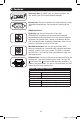
2. Features A B Magnetic, 2-Pole Branch-Rated Breaker (PDUMNH30HV) (PDUMNH30HV & PDUMNH32HV): The Digital Load Meter may be set using the Meter Select switch to display the PDU’s total connected load (all 16 outlets-both LEDs illuminated), or the load carried by either the upper bank (Bank 1 LED illuminated) or lower bank (Bank 2 LED illuminated) of 8 outlet receptacles. If you press and hold the mode selection switch A for 4 seconds, the unit’s IP address will display on the meter B.
2. Features Accessory Slot: An SNMP card, has been installed in the slot, allowing the PDU to be monitored remotely. Factory Port: The port is reserved for configuration by factory authorized personnel only. Do not connect anything to the port. SNMP Card Ports: PS/2 Port: Use this port to connect a Tripp Lite ENVIROSENSE environmental sensor to provide remote temperature/humidity monitoring and a dry contact interface to control and monitor alarm, security and telecom devices. Visit www.tripplite.
3. Installation 3.1 Mounting the PDU The PDU supports five primary mounting configurations: 2U Rack, 1U Rack, 0U Rack, Wall and Under-Counter. Note: Regardless of configuration, the user must determine the fitness of hardware and procedures before mounting. The PDU and included hardware are designed for common rack and rack enclosure types and may not be appropriate for all applications. Exact mounting configurations may vary. 3.
3. Installation 3.1-3 0U Rack Mounting: Use three screws to attach each of the two shorter mounting brackets to the PDU as shown. Mount the PDU vertically by inserting two or more user-supplied screws through the mounting brackets and into mounting points in the rack or rack enclosure. 3.1-3 PDUMNH20HV You may have to remove the screws attaching the mounting brackets to the PDU, change the orientation of the brackets as shown and reattach the brackets.
3. Installation 3.1-5 Under-Counter Mounting: Use three screws to attach each of the two shorter (1U models) or 2U mounting brackets to the PDU as shown. Mount the PDU under the counter by inserting two or more user-supplied screws through the mounting brackets and into secure mounting points. 3.1-5 PDUMNH20HV You may have to remove the screws attaching the mounting brackets to the PDU, change the orientation of the brackets as shown and reattach the brackets.
3. Installation 3.1-7 Cord Retention Shelf Attachment (Optional): Use included screws to attach the cord retention shelf/shelves to the bottom of the front panel of the 1U model or to the top and bottom of the front panel of the PDU (2U models) as shown. 3.1-7 PDUMNH20HV 3.1-7 PDUMNH30HV & PDUMNH32HV 3.1-8 Cord Retention (Optional): If you attached the cord retention shelves, use them to secure the equipment power cords.
3. Installation 3.2-2 NEMA Adapter Connection (Optional - PDUMNH20HV Only): The PDUMNH20HV includes a plug adapter that adds a NEMA L6-20P plug to the input power cord. Use this adapter only if you will be connecting the PDUMNH20HV to a NEMA L6-20R outlet. Insert the IEC 60320 C19 connector A of the adapter into the IEC 60320 C20 connector B of the input power cord.
3. Installation 3.3 Networking the PDU (Only applicable to models with SNMP Network Card installed) For instructions on networking the PDU, please refer to the SNMPWEBCARD Quick Start Guide on the included CD-ROM. 3.4 Testing Network Connection Access PDU with Web Browser: After an IP address has been assigned to the PDU, attempt to access it with a Web browser that supports frames, forms and Java™. Open a Web browser on a computer connected to the LAN and enter the IP address assigned to the PDU.
6. Warranty & Warranty Registration LIMITED WARRANTY Seller warrants this product, if used in accordance with all applicable instructions, to be free from original defects in material and workmanship for a period of 2 years from the date of initial purchase. If the product should prove defective in material or workmanship within that period, Seller will repair or replace the product, in its sole discretion.
Manual del propietario PDUs de Alto Voltaje, Monitoreadas para rack Models: PDUMNH20HV, PDUMNH30HV & PDUMNH32HV 1. Instrucciones de seguridad importantes 14 2. Características 15 3. 3.1 3.2 3.3 3.4 Instalación Montaje de la PDU Conexión de la PDU Conectando Su PDU a la Red Probando la Conexión de Red 18 18 21 23 23 4. 4.1 Configuración y operación Control y monitoreo remoto 23 23 5. Soporte técnico 23 6. Garantía 24 1111 W. 35th Street, Chicago, IL 60609 USA www.tripplite.
1. Instrucciones de seguridad importantes GUARDE ESTAS INSTRUCCIONES Este manual contiene instrucciones y advertencias que deben seguirse durante la instalación, operación y almacenamiento de este producto. La falta de observar estas advertencias podría afectar su garantía. • La PDU proporciona cómodas salidas múltiples, pero NO proporciona protección contra obretensión o ruido en la línea al equipo conectado.
2. Caractéristiques Cordón de alimentación de entrada de CA primaria (PDUMNH32HV): Este cordón se encuentra conectado permanentemente a la PDU y tiene un enchufe 2P + E IEC 309P. Cordón de alimentación de entrada de CA primaria (PDUMNH30HV): Este cordón se encuentra conectado permanentemente a la PDU y tiene un enchufe NEMA L6-30P. Cordón de alimentación de entrada de CA secundaria (PDUMNH20HV): El cordón separable tiene un conector IEC320-C19 A y un conector IEC-320-C20 B .
2. Caractéristiques A B Interruptor magnético de 2 polos, de bifurcación adecuada (PDUMNH30HV) Medidor digital de carga (Amperímetro) (PDUMNH30HV & PDUMNH32HV): Se puede ajustar usando el interruptor selector del medidor para mostrar la carga total conectada al PDU (todos los 16 tomacorrientes con ambos LED iluminados), o la carga transportada ya sea por el banco superior (Banco 1 LED iluminado) o por el banco inferior (Banco 2 iluminado) de 8 receptáculos de tomacorriente.
2. Caractéristiques Ranura Auxiliar: Se ha instalado una tarjeta SNMP en la ranura, permitiendo que el PDU sea monitoreada a distancia. Puerto de fábrica: Este puerto está reservado para la configuración, la cual deberá realizar solamente el personal autorizado por la fábrica. No conecte nada al puerto.
3. Instalación 3.1 Montaje de la PDU La unidad PDU es compatible con cinco configuraciones de instalación principales: Rack de 2U, Rack de 1U, Rack de 0U, en pared y debajo de mostrador. Nota: El usuario debe determinar la idoneidad de los materiales y accesorios así como de los procedimientos antes del montaje. La PDU y el material incluido están diseñados para racks (bastidores) y cajas de rack (bastidor) comunes, y pueden no ser apropiados para todas las aplicaciones. 3.
3. Instalación 3.1-3 Instalación de Rack de 0U: Use tres tornillos para instalar cada uno de los dos soportes más cortos al PDU como se muestra. Instale el PDU verticalmente insertando dos o más tornillos, proporcionados por el usuario, a través de los soportes de instalación y en los puntos de instalación en el rack o estante de rack. 3.
3. Instalación 3.1-5 Instalación Debajo de Mostrador: Use tres tornillos para fijar cada uno de los dos soportes de instalación más cortos (modelos 1U o 2U) al PDU como se indica. Instale la unidad PDU debajo del mostrador insertando dos o más tornillos, suministrados por el usuario, a través de los soportes de instalación y en los puntos de instalación seguros. 3.
3. Instalación 3.1-7 Instalación de la Bandeja de Retención de Cables (Opcional): Use los tornillos incluidos para instalar la bandeja o bandejas de retención de cables a la parte inferior del panel frontal del modelo 1U o en la parte superior y en la parte inferior del panel frontal del PDU (modelos 2U) como se muestra. 3.1-7 PDUMNH20HV 3.1-7 PDUMNH30HV & PDUMNH32HV 3.
3. Instalación 3.2-2 Adaptador de conexión NEMA (Opcional: para PDUMNH20HV exclusivamente): El PDUMNH20HV incluye un adaptador que incorpora una clavija NEMA L6-20P al cable de alimentación de entrada. Utilice este adaptador solamente si va a conectar el PDUMNH20HV a una toma de corriente NEMA L6 20R. Inserte el conector IEC 60320 C19 A del adaptador en el conector IEC 60320 C20 B del cable de alimentación de entrada.
3. Instalación 3.3 Conectando Su PDU a la Red (Solo aplicable a modelos con tarjeta de red SNMP instalada) Para instrucciones sobre instalación del PDU en red, por favor consulte la Guía de Inicio Rápido de SNMPWEBCARD en el CD-ROM incluido. 3.4 Probando la Conexión de Red Acceda al PDU con el Navegador de Red: Después que una dirección IP ha sido asignada al PDU, trate de acceder con navegador de Web que soporte frames [marcos], forms [formas] y Java™.
6. Garantía GARANTÍA LIMITADA El vendedor garantiza que este producto, si se emplea de acuerdo con todas las instrucciones aplicables, no tendrá defectos en materiales ni mano de obra por un período de 2 años (salvo para baterías internas del UPS fuera de EE.UU. y Canadá, 1 año) a partir de la fecha de compra. Si se verifica que el producto tiene defectos en los materiales o en la mano de obra dentro de dicho período, el vendedor reparará o reemplazará el producto, a su sola discreción.
Manuel du propriétaire Unité de distribution (PDU) en baie contrôlée par haute tension Models: PDUMNH20HV, PDUMNH30HV & PDUMNH32HV 1. Importantes consignes de sécurité 26 2. Caractéristiques 27 3. 3.1 3.2 3.3 3.4 Installation Montage de la PDU Connexion de la PDU Mise en réseau de la PDU Probando la Conexión de Red 30 30 33 35 35 4. 4.1 Configuration et fonctionnement Surveillance et commande à distance 35 35 5. Assistance technique 35 6. Garantie 36 1111 W.
1. Importantes consignes de sécurité CONSERVER CES DIRECTIVES Ce manuel contient des instructions et des mises en garde que vous devez respecter durant l’installation, l’utilisation et l’entreposage de ce produit. Ne pas tenir compte de ces mises en garde pourrait affecter votre garantie. • L’unité PDU offre de nombreuses prises pratiques mais elle N’offre PAS de protection contre les surtensions transitoires et les parasites à l’équipement connecté.
2. Caractéristiques Cordon d’alimentation d’entrée primaire CA (PDUMNH32HV) : Ce cordon est fixé en permanence à la PDU et dispose d’une fiche 2P + E IEC 309P. Cordon d’alimentation d’entrée primaire CA (PDUMNH30HV) : Ce cordon est fixé en permanence à la PDU et dispose d’une fiche NEMA L6-30P. Cordon d’alimentation d’entrée secondaire CA (PDUMNH20HV) : Le cordon amovible dispose d’un connecteur IEC-320-C19 A et d’un connecteur IEC-320-C20 B .
2. Caractéristiques A B Disjoncteur Magnétique, 2-Pôles (PDUMNH30HV) Indicateur de charge numérique (Ampèremètre) (PDUMNH30HV & PDUMNH32HV): Il peut être calibré en utilisant le commutateur « Meter Select » pour afficher la charge totale reliée à la PDU (chacune des 16 sortie-les deux voyants DEL allumés), ou la charge portée par la batterie supérieure (voyant DEL de la batterie 1 illuminé) ou la batterie inférieure (voyants de la batterie 2 illuminés) des 8 prises de sortie.
2. Caractéristiques Fente pour accessoires : Une carte SNMP a été installée dans la fente, permettant à la PDU d’être surveillée à distance. Port d’usine : Ce port est réservé pour la configuration en usine uniquement par du personnel autorisé. Ne rien connecter à ce port.
3. Installation 3.1 Montage de la PDU La PDU peut être montée selon cinq configurations principales : bâti en 2U, bâti en 1U, bâti en 0U (vertical), au mur et sous le comptoir. Nota : L’utilisateur doit déterminer la compatibilité de la quincaillerie et les procédures avant d’effectuer l’installation. L’unité PDU et la quincaillerie incluse sont conçues pour des types de bâti et boîtier courants et peuvent ne pas convenir à toutes les applications. 3.
3. Installation 3.1-3 Montage en bâti 0U : Utilisez trois vis pour attacher chacun des deux supports de montage courts à la PDU tel qu’illustré. Montez la PDU verticalement en insérant deux vis ou plus fournies par l’utilisateur dans les points de montage du bâti ou de l’enceinte de support. 3.1-3 PDUMNH20HV Vous devrez peut-être ôter les vis attachant les supports de montage à la PDU, changer l’orientation des supports tel qu’illustré et rattacher les supports.
3. Installation 3.1-5 Montage sous le comptoir : Utilisez trois vis pour attacher chacun des deux supports de montage les plus courts (modèles 1U) ou les supports de montage 2U à la PDU tel qu’illustré. Installez la PDU sous le comptoir en insérant 2 vis ou plus fournies par l’utilisateur dans les supports de montage et ensuite dans les points de montage sécurisés. 3.
3. Installation 3.1-7 Tablette de retenue de cordon d’alimentation (facultatif) : Utilisez les vis incluses pour attacher la tablette/étagères de retenue du cordon d’alimentation au fond du panneau avant du modèle 1U ou sur le haut ou le bas du panneau avant de la PDU (modèles 2U) tel qu’illustré. 3.1-7 PDUMNH20HV 3.1-7 PDUMNH30HV & PDUMNH32HV 3.
3. Installation 3.2-2 Branchement de l’adaptateur NEMA (en option- PDUMNH20HV uniquement) : Le PDUMNH20HV comprend un adaptateur permettant d’ajouter une fiche NEMA L6-20P au cordon d’alimentation. N’utilisez cet adaptateur que pour connecter le PDUMNH20HV à une prise NEMA L6-20R. Insérez le connecteur A CEI 60320 C19 de l’adaptateur dans le connecteur B CEI 60320 C20 du cordon d’alimentation.
3. Installation 3.3 Mise en réseau de l’unité de distribution (Applicable uniquement aux modèles avec carte réseau SNMP installée) Pour des instructions sur le réseautage de la PDU, veuillez vous référer au Guide Rapide de démarrage de la SNMPWEBCARD sur le CD-ROM ci-joint. 3.4 Test de la connexion réseau Accès à la PDU à l’aide d’un navigateur Web : Une fois une adresse IP affectée à la carte, essayer d’y accéder à l’aide d’un navigateur Web qui supporte les cadres, les masques de saisie et Java™.
6. Garantie GARANTIE LIMITÉE Le vendeur garantit que ce produit, s’il est utilisé selon toutes les directives applicables, est exempt de défauts d’origine de matériel et de main-d’oeuvre pour une période de 2 ans (à l’exception des batteries interne du système UPS hors des É. U. et du Canada, 1 an) à partir de la date initiale d’achat. Si le produit s’avère défectueux en matériel ou en main-d’oeuvre durant cette période, le vendeur réparera ou remplacera le produit à sa discrétion.