e nty : anc rra ationr a ch duct— a o o r r f W st ay e p nty gi od Lit rra Renline t Tripp m/wa o o E er FRE lite.c ist p reg in a .trip w w to ww Owner’s Manual ™ SmartOnline True On-Line Tower UPS Systems Not suitable for mobile applications. Important Safety Instructions 2 Installation 3 Basic Operation 5 Troubleshooting 9 Battery Replacement 11 Storage and Service 11 Warranty Registration 12 Español 13 Français 25 1111 W. 35th Street, Chicago, IL 60609 USA 773.869.
Important Safety Instructions SAVE THESE INSTRUCTIONS This manual contains instructions and warnings that should be followed during the installation, operation and storage of all Tripp Lite UPS Systems. Failure to heed these warnings will void your warranty. UPS Location Warnings • I nstall your UPS indoors, away from excess moisture or heat, conductive contaminants, dust or direct sunlight. • F or best performance, keep the indoor temperature between 32º F and 104º F (0º C and 40º C).
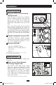
Installation Important Safety Instructions Connection and Start-Up 1 Plug your UPS’s line cord into an electrical outlet. Your UPS must be connected to a dedicated circuit of sufficient amperage. Note, however, that the select models may be fitted with different plug types. Refer to the “OP Rating/ Plug Rating” chart printed on the top of your UPS. Once your UPS is plugged in, the fan and all Indicator Lights will turn ON.
Installation (continued) Optional Connections (continued) 2 USB and RS-232 Serial Communications Use the included USB cable (see 2a ) and/or DB9 serial cable (see 2b ) to connect the communication port of your computer to the communication port of your UPS. Install on your computer the Tripp Lite PowerAlert Software appropriate to your computer's operating system. 3 Your model may differ. Your model may differ.
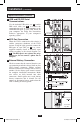
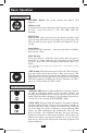
Basic Operation Front Panel Switches “ON/TEST” Button: This switch controls four separate UPS functions: UPS Power ON To turn the UPS on, press this button, hold it for several seconds until you hear a beep, then release it. The “ON LINE” LED will illuminate. UPS Self-Test During normal on-line operation, press this button and hold it until you hear a beep. This initiates a 10-second self-test of the battery. The UPS will shift to battery power (all LEDs will illuminate) for ten seconds.
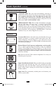
Basic Operation Front Panel Indicator Lights (continued) continued “BYPASS” LED: This yellow light will flash to indicate that the DC/ AC inverter is deactivated and the UPS is in the “Bypass” mode.
Basic Operation Front Panel Indicator Lights (continued) continued “ON BATT” LED: This green light will illuminate constantly to indicate that AC line voltage is not present and your UPS is providing your equipment with battery power. The UPS will also beep every two seconds, unless silenced by the “ON/TEST” Button. When this light is illuminated, you can monitor the battery charge level of your UPS on the “BATT ACTIVE METER” LEDs.
Basic Operation Rear Panel (continued) continued NEMA 5-15R AC Receptacles (Varied by Model): These 15-, 20- and 30-amp receptacles provide your connected equipment with pure sine-wave AC output from the AC line during normal operation and from battery power during blackouts and severe brownouts. Power provided at these outlets is filtered to protect connected equipment against damaging surges and line noise. The receptacles are divided into numbered load banks, as labelled on the unit.
Troubleshooting The UPS’s control panel lights will turn on in the sequences below to signal that the UPS is having operational difficulties. Lights (On/Flashing) and Condition Solution On: REPLACE BATT Condition: Replace Battery Let the UPS system charge for at least 12 hours and perform a self test using the "ON/Test Switch". If the light continues to stay on, contact Tripp Lite for service. On: BATT LOW, ON BATT Condition: Battery Low Prepare for imminent UPS shutdown.
Troubleshooting (continued) Lights (On/Flashing) and Condition Solution On: BYPASS, LINE Flashing: FAULT Condition: On Bypass due to High Internal Temperature Check the UPS to be sure that there is adequate space for air to circulate near the vents and that the fan is working properly. Restart the UPS. Flashing: LINE Condition: Input Abnormal This indicates that utility power is too high or low for the UPS to operate in BYPASS mode, so if an inverter failure occurs, the UPS will deliver no output.
Battery Replacement 1 Your model may differ. 2 Your model may differ. 3 Battery Replacement Door: Under normal conditions, the original battery in your UPS will last several years. Battery replacement should be performed only by qualified service personnel. Refer to “Battery Warnings” in the Safety section. Should your UPS require battery replacement, visit Tripp Lite on the Web at www.tripplite.com/support/ battery/index.cfm to locate the specific replacement battery for your UPS.
Warranty Registration Visit www.tripplite.com/warranty today to register the warranty for your new Tripp Lite product. You'll be automatically entered into a drawing for a chance to win a FREE Tripp Lite product!* * No purchase necessary. Void where prohibited. Some restrictions apply. See website for details. Regulatory Compliance Identification Numbers: For the purpose of regulatory compliance certifications and identification, your Tripp Lite product has been assigned a unique series number.