
Owner's Manual


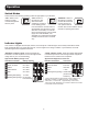

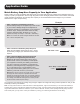


Table Of Contents
- Important Safety Instructions
- Feature Identification
- Operation
- Application Guide
- Mounting (optional)
- Battery Connection
- Troubleshooting
- Specifications
- Service
- Maintenance
- Warranty and Product Registration
- Important Safety Instructions
- Feature Identification
- Operation
- Application Guide
- Mounting (optional)
- Battery Connection
- Troubleshooting
- Specifications
- Service
- Maintenance
- Warranty and Product Registration
- Important Safety Instructions
- Feature Identification
- Operation
- Application Guide
- Mounting (optional)
- Battery Connection
- Troubleshooting
- Specifications
- Service
- Maintenance
- Warranty and Product Registration

5
“BATTERY” Indicator Lights: These three lights will
illuminate in several sequences to show the approximate
charge level of your connected battery:
Approximate Battery Charge Level
†
Indicator Illuminated Battery Capacity
1
Green 91%–Full
2
Green & Yellow 81%–90%
3
Yellow 61%–80%
4
Yellow & Red 41%–60%
5
Red 21%–40%
6
Flashing Red (slowly)* 1%–20%
7
Flashing Red (quickly)** 0% (Inverter
has shutdown)
“LOAD” Indicator Lights: These three lights will illuminate
in several sequences to show the approximate equipment
load level on the Inverter’s AC receptacles.
Approximate Equipment Load Level
Indicator Illuminated Load Level
1
Green 0%-50%
2
Green & Yellow 51%-75%
3
Yellow 76%-90%
4
Red > 90%
5
Flashing Red (quickly)** OVERLOAD
(Inverter has
shutdown)
† Charge levels listed are approximate. Actual conditions vary
depending on battery condition and load. * Approximately
½ second on, ½ second off. ** Approximately ¼ second on,
¼ second off. See “Resetting Your Inverter to Restore AC Power”
to reset after Inverter shut down.
Operation
Switch Modes
Switch between the following operating modes as appropriate to your situation:
“ON”: Switch to this
setting to provide
connected equipment
with AC power.
“OFF”: Switch to
this setting to shut
down the Inverter
completely, preventing
it from drawing power
from the batteries. Use this switch to
automatically reset the unit if it shuts
down due to low battery or overload.
Use an optional remote control module
(Tripp Lite model APSRM4, sold
separately or included with PV3000HF
models) to reset unit due to overload
only.
“REMOTE”: Switch to
this setting to remotely
monitor and control the
Inverter with the use
of an optional remote
module. See remote module’s owner’s
manual for operating instructions.
Indicator Lights
Your Inverter is equipped with a simple, intuitive, user-friendly set of indicator lights. These easily-remembered “traffic
light” signals will allow you, shortly after first use, to tell at a glance the charge condition of your batteries, as well as
ascertain approximate equipment load level.
1
4
7
2
5
3
6
1
4
2
5
3