Owner’s Manual B093-00X-2E4U-X Resilience Gateway B097-016/048 Console Server B098-016/048 and B098-016-V Infrastructure Manager WARRANTY REGISTRATION Register your product today and be automatically entered to win an ISOBAR® surge protector in our monthly drawing! tripplite.com/warranty 1111 W. 35th Street, Chicago, IL 60609 USA • tripplite.com/support Copyright © 2022 Tripp Lite. All rights reserved.
Table of Contents 1. Introduction 2. Installation 2.1 2.2 Models Power Connection 2.2.1 2.2.2 2.3 2.4 2.5 2.6 Models with Internal AC Power Supplies Models with External Power Supplies 3.2 11 11 12 3.1.1 3.1.2 12 13 Administrator Setup Network Configuration 3.3.1 3.3.2 3.4 3.5 3.6 3.7 Change Default Root System Password Set Up New Administrator Name the System IPv6 Configuration Dynamic DNS (DDNS) Configuration 4.3 4.
Table of Contents 5. Firewall, Failover and OOB Access 5.1 5.2 5.3 5.4 5.5 5.6 Dialup Modem Connection OOB Dial-In Access 72 72 5.2.1 5.2.2 5.2.3 5.2.4 5.2.5 73 75 75 76 76 5.7 5.8 Configure Dial-In PPP Using SDT Connector Client Set Up Windows XP or Later Client Set Up Earlier Windows Clients Set Up Linux Clients Dial-Out Access 76 5.3.1 5.3.
Table of Contents 7. Alerts, Auto-Response and Logging 126 7.1 7.2 Configure Auto-Response Check Conditions 7.2.1 7.2.2 7.2.3 7.2.4 7.2.5 7.2.6 7.2.7 7.2.8 7.2.9 7.2.10 7.2.11 7.2.12 7.2.13 7.2.14 7.
Table of Contents 10. Nagios Integration 181 10.1 Nagios Overview 10.2 Configuring Nagios Distributed Monitoring 181 181 10.2.1 10.2.2 10.2.3 10.2.4 10.2.5 10.2.6 182 Enable Nagios on the Console Server Enable NRPE Monitoring Enable NSCA Monitoring Configure Selected Serial Ports for Nagios Monitoring Configure Selected Network Hosts for Nagios Monitoring Configure the Upstream Nagios Monitoring Host 183 184 185 185 186 10.
Table of Contents 15.3 Raw Access to Serial Ports 15.3.1 15.3.2 Access to Serial Ports Accessing the Console/ Modem Port 15.4 IP Filtering 15.5 SNMP Status Reporting 15.5.1 15.5.2 15.5.3 15.5.4 Retrieving Status Information using SNMP Check Firewall Rules Enable SNMP Service Adding Multiple Remote SNMP Managers 243 244 245 245 247 248 15.6.1 15.6.2 15.6.3 15.6.4 15.6.5 15.6.6 15.6.7 15.6.8 248 249 250 250 251 253 253 256 15.
Important Safety Instructions Please take care to follow the safety precautions below when installing and operating the console server: - Do not remove the metal covers. There are no operator serviceable components inside. Opening or removing the cover may expose you to dangerous voltage that may cause fire or electric shock. Refer all service to Tripp Lite qualified personnel. - To avoid electric shock the power cord protective grounding conductor must be connected through to ground.
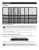
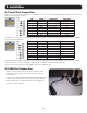
2. Installation 2.1 Models USB 10/100 Ethernet 10/100/1000 Ethernet Flash Console Port V.
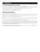
2. Installation 2.2.2 Models with External Power Supplies Some console servers use an external 12V wall-mount power supply (see 2.1 Models for model listing). These models include a selection of wall socket adapters for each geographic region (North America, Europe, U.K., Japan and Australia). The power supply unit’s 12V DC connector plugs into the 12V DC (PWR) power jack located on the side of the unit. • Plug in the power supply AC power cable and the DC power cable.
2. Installation 2.4 Serial Port Connection Tripp Lite console servers use the RJ45 pin-out standard used by Cisco. Use straight-through RJ45 cabling to connect to Cisco, Juniper, SUN equipment and more. PIN 1 2 3 4 5 6 7 8 SIGNAL CTS DSR RXD GND GND TXD DTR RTS DEFINITION Clear To Send Data Set Ready Receive Data Signal Ground Signal Ground Transmit Data Data Terminal Ready Request To Send DIRECTION Input Input Input NA NA Output Output Output The B098 console servers can select this pinout.
2. Installation 2.6 Fitting Cellular SIM and Antennas The B093 -V models and the B098-016-V have internal 4G LTE cellular modems. Each cellular modem requires at least one SIM card to be installed and two external cellular antennas to be attached. For more detail: 2.6.1 B093-00X-2E4U-V Models B093-008-2E4U-V models come with internal 4G LTE modems and dual mini-SIM card slots. -V models work with Verizon USA by default but can be reconfigured to work with AT&T USA.
3. System Configuration This chapter provides step-by-step instructions for the initial configuration of your console server and how to connect it to the Management or Operational LAN. Notes: • System configuration must be done by a person with Administrator access. • For guidance on configuring large numbers of Tripp Lite console servers and/or automating provisioning, sections 15.15 Bulk Provisioning and 15.16 Zero Touch Provisioning. 3.
3. System Configuration Now add a static entry to the ARP table and ping the console server to assign the IP address to the console server. In the example below, a console server has a MAC Address 00:06:67:12:DA:F1 (designated on the label on the bottom of the unit) and we are setting its IP address to 192.168.100.23. Also the computer issuing the arp command must be on the same network segment as the console server (that is, have an IP address of 192.168.100.xxx). • Type arp -s 192.168.100.
3. System Configuration 3.2 Administrator Setup 3.2.1 Change Default Root System Password For security reasons, only the Administrator user named root can initially log into your console server. Also, only users who know the root password can access and reconfigure the console server.
3. System Configuration 3.2.3 Name the System Select System: Administration. Enter a System Name and System Description for the console server to give it a unique ID and make it simple to identify. Note: The System Name can contain from 1 to 64 alphanumeric characters (you can also use the special characters “-” “_” and “.”). There are no restrictions on the characters that can be used in the System Description (which can contain up to 254 characters).
3. System Configuration 3.3 Network Configuration Enter an IP address for the principal Ethernet (LAN/Network/Network1) port on the console server, or enable its DHCP client so that it automatically obtains an IP address from a DHCP server on the network it is to be connected to. On the System: IP menu, select the Network Interface page, then check DHCP or Static for the Configuration Method. If you selected Static, you must manually enter the new IP Address, Subnet Mask, Gateway and DNS server details.
3. System Configuration 3.3.1 IPv6 Configuration By default, the console server Ethernet interfaces support IPv4. However, they can also be configured for IPv6 operation: • On the System: IP menu, select General Settings page and check Enable IPv6. • You will then need to configure the IPv6 parameters on each interface page. 3.3.
3. System Configuration You can now enable and configure DDNS on any of the Ethernet or cellular network connections on the console server (by default DDNS is disabled on all ports): • Select the DDNS service provider from the dropdown Dynamic DNS list on the System: IP or System: Dial menu. • In DDNS Hostname, enter the fully qualified DNS hostname for your console server e.g. your-hostname.dyndns.org. • Enter the DDNS Username and DDNS Password for the DDNS service provider account.
3. System Configuration 3.4 Services and Service Access The Administrator can access the console server, connected serial ports and managed devices by using a range of access protocols/services. For each such access: • The particular service must first be configured and enabled to run on the console server. • Then, access through the firewall must be enabled for each network connection. To enable and configure a service: • Select the Service Settings tab on the System: Services page.
3. System Configuration Telnet By default, the Telnet service is running. However, by default, the service is disabled on all network interfaces. Telnet can be used to give the Administrator access to the system command line shell. While this may be suitable for a local direct connection over a management LAN, it is recommended this service be disabled if the console server is to be remotely administered. This service may also be useful for local Administrator and User access to selected serial consoles.
3. System Configuration The Services Access settings can now be set to allow or block access. This specifies which (enabled) services the Administrator can use over each network interface - to connect to the console server and through the console server to attached serial and network-connected devices. • Select the Service Access tab on the System: Services page. Note: With firmware releases pre-3.5.3, the Service Access tab is found on the System: Firewall page.
3. System Configuration • In the example shown below, local administrators on local Management LAN have direct telnet access to the console server (and attached serial ports), while remote administrators using dial-in or cellular have no such telnet access (unless they set up a VPN). • Respond to ICMP echoes (i.e. ping) Service access options can be configured at this stage. This allows the console server to respond to incoming ICMP echo requests. Ping is enabled by default.
3. System Configuration 3.5 Communications Software You have configured access protocols for the Administrator client to use when connecting to the console server. User clients (who you may set up later) will also use these protocols when accessing console server serial attached devices and network attached hosts. Therefore, you will need to have appropriate communications software tools set up on the Administrator (and User) client’s computer.
3. System Configuration 3.5.2 PuTTY Communications packages like PuTTY can also be used to connect to the console server command line (and to connect serially attached devices, refer to 4. Serial Port, Host, Device and User Configuration). PuTTY is a freeware implementation of telnet and SSH for Win32 and UNIX platforms. It runs as an executable application without needing to be installed onto your system. PuTTY (the telnet and SSH client itself) can be downloaded at http://www.tucows.com/preview/195286.
3. System Configuration A new Connection Profile dialog box will appear where you can type in the host name or IP address (for the console server unit) and the TCP port that the SSH session will use (port 22). Type in your username, choose password authentication and click Connect. You may receive a message about the host key fingerprint, and you will need to select Yes or Always to continue.
3. System Configuration The Management LAN features are all disabled by default. To configure the Management LAN gateway: • Select the Management LAN Interface page on the System: IP menu and uncheck Disable. • Configure the IP Address and Subnet Mask for the Management LAN (but leave the DNS fields blank). • Click Apply. The management gateway function is now enabled with default firewall and router rules.
3. System Configuration 3.6.2 Configure the DHCP Server All Tripp Lite devices host a DHCP server. However, this setting is disabled by default. The DHCP server enables the automatic distribution of IP addresses to devices on the Management LAN that are running DHCP clients. To enable the DHCP server: • On the System: IP menu, select the Management LAN page and click the Disabled label in the DHCP Server field (or go directly to the System: DHCP Server menu). • Check Enable DHCP Server.
3. System Configuration The DHCP server will sequentially issue IP addresses from a specified address pool(s): • Click Add in the Dynamic Address Allocation Pools field. • Enter the DHCP Pool Start Address and End Address, then click Apply. The DHCP server also supports pre-assigning IP addresses to be allocated only to specific MAC addresses and reserving IP addresses to be used by connected hosts with fixed IP addresses.
3. System Configuration 3.6.3 Select Failover or Broadband OOB The B093 and B098 console servers provide a failover option. In the event a problem arises while using the main LAN connection for accessing the console server, an alternate access path is automatically used. By default, the failover is not enabled. To enable: • Select the Network page on the System: IP menu. • Now select the Failover Interface to be used in the event of an outage on the main network.
3. System Configuration 3.6.4 Aggregating the Network Ports By default, the console server’s Management LAN network ports can only be accessed using SSH tunneling /port forwarding or by establishing an IPsec VPN tunnel to the console server. However, all wired network ports on the console servers can be aggregated by being bridged or bonded. By default, Interface Aggregation is disabled on the System: IP General Settings menu.
3. System Configuration 3.6.5 Static Routes Firmware 3.4 and later support static routes, which provide a quick way to route data from one subnet to a different subnet. You can hard code a path that specifies to the console server/router to get to a certain subnet by using a certain path. This may be useful for remotely accessing various subnets at a remote site when being accessed using the cellular OOB connection.
3. System Configuration A backup configuration file — model-name_iso-format-date_config.opg — is downloaded from the Tripp Lite device to the local system. Alternately, you can save the configuration as an xml file: • Select System > Configuration Backup > XML Configuration. An editable field containing the configuration file in XML format is presented. • Click into the field to make it active.
3. System Configuration Prepare a USB Drive and Create the X.509 Certificate and Private Key • Generate the CA certificate so the client and server Certificate Signing Requests (CSRs) can be signed. # cp /etc/ssl/openssl.cnf . # mkdir -p exampleCA/newcerts # echo 00 > exampleCA/serial # echo 00 > exampleCA/crlnumber # touch exampleCA/index.txt # openssl genrsa -out ca.key 8192 # openssl req -new -x509 -days 3650 -key ca.key -out demoCA/cacert.pem \ -subj /CN=ExampleCA # cp demoCA/cacert.pem ca-bundle.
4. Serial Port, Host, Device and User Configuration The console server enables access and control of serially attached devices and network-attached devices (hosts). The Administrator must configure access privileges for each of these devices, and specify the services that can be used to control the devices. The Administrator can also set up new users and specify each user’s individual access and control privileges. 4.
4. Serial Port, Host, Device and User Configuration If the console server has been configured with distributed Nagios monitoring enabled, then you will also be presented with Nagios Settings options to enable assigned services on the Host to be monitored (see section 10. Nagios Integration for more information). 4.1.1 Common Settings There are a number of common settings for each serial port. These are independent of the mode in which the port is being used.
4. Serial Port, Host, Device and User Configuration Logging Level This specifies the level of information to be logged and monitored (refer to 7. Alerts and Logging). Telnet When the telnet service is enabled on the console server, a telnet client on a User’s or Administrator’s computer can connect to a serial device attached to this serial port on the console server. The telnet communications are unencrypted so this protocol is generally recommended only for local or VPN tunneled connections.
4. Serial Port, Host, Device and User Configuration You can also use standard communications packages like PuTTY to set a direct telnet (or SSH) connection to the serial ports. Note: PuTTY also supports telnet (and SSH). The procedure to set up a telnet session is simple. Enter the console server’s IP address as the ‘Host Name (or IP address)’. Select Telnet as the protocol and set the TCP port to 2000, plus the physical serial port number (i.e. 2001 to 2048). Click the Open button.
4. Serial Port, Host, Device and User Configuration Or, by typing username=fred:serial and ssh port = 22, the User is presented with a port selection option: This syntax enables Users to set up SSH tunnels to all serial ports with only a single IP port 22 having to be opened in their firewall/gateway Note: In Console Server mode, when you connect to a serial port, you connect via pmshell. To generate a BREAK on the serial port, type the character sequence ~b. If connecting over OpenSSH, type ~~b.
4. Serial Port, Host, Device and User Configuration Web Terminal Selecting Web Terminal enables web browser access to the serial port via Manage: Devices: Serial using the management console’s built in AJAX terminal. Web Terminal connects as the currently authenticated management console user and does not re-authenticate. See section 13.3 Terminal Connection for details. IP Alias Enable access to the serial port using a specific IP address specified in CIDR format.
4. Serial Port, Host, Device and User Configuration 4.1.3 SDT Mode This secure tunneling setting allows port forwarding of RDP, VNC, HTPP, HTTPS, SSH, telnet and other LAN protocols to computers locally connected to the console server by their serial COM port. However, such port forwarding requires a PPP link to be set up over this serial port. For configuration details, refer to section 6.4 SDT Connector: Using Telnet or SSH to Connect Devices that are Serially Attached to the Console Server. 4.1.
4. Serial Port, Host, Device and User Configuration 4.1.6 Serial Bridging Mode With serial bridging, the serial data on a console server’s serial port is organized in network packets and transported over a network to a second console server, effectively allowing the two console servers to act as a virtual serial cable on an IP network. One console server is configured to be the Server. The Server serial port to be bridged is set in Console Server mode with either RFC2217 or RAW enabled (refer to 4.1.
4. Serial Port, Host, Device and User Configuration 4.1.8 USB Consoles B093, B097, and B098 model console servers running firmware 3.16.5 or later support USB console connections to devices from a wide range of vendors, including Cisco, HP, Dell and Brocade. All the USB ports on these console servers can also function as plain RS-232 serial ports when a USB-to-serial adapter is connected.
4. Serial Port, Host, Device and User Configuration 4.2 Add and Edit Users The Administrator uses this menu selection to set up, edit and delete users, and define the access permissions for each of these users. Users can be authorized to access specified services, serial ports, power devices and specified network-attached hosts. These users can also be given full Administrator status (with full configuration, management and access privileges).
4. Serial Port, Host, Device and User Configuration 4. The Administrator can also set up additional groups with permissions to a specific power device, serial port and host access. However, users in these additional groups do not have any access to the Management Console menu nor do they have any command line access to the console server itself. 5. The Administrator can also set up users with specific power device, serial port and host access permissions, who are not a member of any Groups.
4. Serial Port, Host, Device and User Configuration 4.2.2 Set Up New Users To set up new users, and assign users to particular groups: • Select Serial & Network: Users & Groups to display the configured groups and user. • Click Add User to add a new user. • Add a Username for each new user. You may also include information related to the user (e.g., contact details) in the Description field. Note: The username can contain from 1 to 127 alphanumeric characters (special characters “-” “_” and “.
4. Serial Port, Host, Device and User Configuration Note: There are no specific limits on the number of users you can set up, nor on the number of users per serial port or host. Multiple users (Users and Administrators) can control/monitor the one port or host. Similarly, there are no specific limits on the number of groups. Each user can be a member of multiple groups (in which case, they assume the cumulative access privileges of each of those groups). A user does not have to be a member of any groups.
4. Serial Port, Host, Device and User Configuration Click Add Host to enable access to a new host (or select Edit to update the settings for existing host). Enter the IP Address or DNS Name and a Host Name (up to 254 alphanumeric characters) for the new network-connected host. You can optionally enter a Description. Add or edit the Permitted Services (or TCP/UDP port numbers) authorized for controlling this host. Only these permitted services will be forwarded by SDT to the host.
4. Serial Port, Host, Device and User Configuration 4.5 Trusted Networks The Trusted Networks facility provides an option to assign specific IP addresses that users (Administrators and Users) must be located in order to have access to console server serial ports: • Select Serial & Network: Trusted Networks. • To add a new trusted network, select Add Rule. Note: In the absence of rules, there are no access limitations to the IP address for which Users or Administrators can be located.
4. Serial Port, Host, Device and User Configuration If you wish to allow all users operating from within a specific range of IP addresses (any of the 30 addresses from 204.15.5.129 to 204.15.5.158) to be permitted connection to the assigned port: Host /Subnet Address 204.15.5.128 Subnet Mask 255.255.255.224 • Click Apply. Note: The above trusted networks will limit access by Users and Administrators to the console serial ports.
4. Serial Port, Host, Device and User Configuration 4.6.1 Automatically Generate and Upload SSH keys To set up public key authentication, you must first generate an RSA or DSA key pair and upload them into the Primary and Secondary console servers. This can all be done automatically from the Primary unit: • Select System: Administration on the Primary unit’s management console. • Check Generate SSH keys automatically and click Apply.
4. Serial Port, Host, Device and User Configuration 4.6.2 Manually Generate and Upload SSH Keys Alternately, if you have a RSA or DSA key pair you can manually upload them to the Primary and Secondary console servers. Note: If you do not already have RSA or DSA key pair and you do not wish to use you will need to create a key pair using ssh-keygen, PuTTYgen or a similar tool as detailed in 15.6 Secure Shell (SSH) Public Key Authentication.
4. Serial Port, Host, Device and User Configuration 4.6.3 Configure the Secondary Units and their Serial Ports To begin setting up the Secondary units and configuring Secondary serial ports from the Primary console server: • Select Serial & Network: Cascaded Ports on the Primary unit’s management console: • To add clustering support, select Add Slave (Secondary).
4. Serial Port, Host, Device and User Configuration 4.6.4 Managing the Secondary Serial Ports The Primary console server is in control of the Secondary units’ serial ports. For example, when changing a User’s access privileges or editing any serial port setting on the Primary unit, the updated configuration files will be sent out to each Secondary in parallel.
4. Serial Port, Host, Device and User Configuration To edit an existing device and add a new connection: • Select Edit on the Serial & Network: Managed Devices and click Add Connection. • Select the connection type for the new connection (Serial, Network Host, UPS or RPC). Then select the specific connection from the presented list of configured unallocated hosts/ports/outlets.
4. Serial Port, Host, Device and User Configuration Note: To set up a new serially connected RPC, UPS or EMD device, first configure the serial port, designate it as a device, and then enter a name and description for that device in the Serial & Network: RPC Connections (or UPS Connections or Environmental). When applied, this will automatically create a corresponding new managed device with the same name/description as the RPC/UPS host (refer to 8. Power, Environment and Digital I/O).
4. Serial Port, Host, Device and User Configuration Click Add and complete the Add IPsec Tunnel screen. Enter any descriptive name you wish to identify the IPsec Tunnel you are adding, such as WestStOutlet-VPN. Select the Authentication Method to be used, either RSA digital signatures or a Shared secret (PSK). • If you select RSA, you will be asked click here to generate keys. This will generate an RSA public key for the console server (the Left Public Key).
4. Serial Port, Host, Device and User Configuration In Authentication Protocol, select the authentication protocol to be used. Either authenticate as part of ESP (Encapsulating Security Payload) encryption or separately using the AH (Authentication Header) protocol. Enter a Left ID and Right ID. The local host/gateway and remote host/gateway use this identifier for IPsec negotiation and authentication. Each ID must include a ‘@’ and can include a fully qualified domain name preceded by ‘@’ (e.g.
4. Serial Port, Host, Device and User Configuration 4.9.1 Enable the OpenVPN Select OpenVPN on the Serial & Networks menu. Click Add and complete the Add OpenVPN Tunnel screen. Enter any descriptive name you wish to identify the OpenVPN Tunnel you are adding, for example NorthStOutlet-VPN. Select the authentication method to be used. To authenticate using certificates, select PKI (X.509 Certificates) or select Custom Configuration to upload custom configuration files.
4. Serial Port, Host, Device and User Configuration For a server you may also need dh1024.pem (Diffie Hellman parameters). Refer to http://openvpn.net/easyrsa.html for a guide on basic RSA key management. For alternative authentication methods, go to http://openvpn.net/index.php/ documentation/howto.html#auth. For more information, go to http://openvpn.net/howto.html. • Select the Device Driver to be used, either Tun-IP or Tap-Ethernet.
4. Serial Port, Host, Device and User Configuration To enter authentication certificates and files, Edit the OpenVPN tunnel. Select the Manage OpenVPN Files tab. Upload or browse to relevant authentication certificates and files. Click Apply to save changes. Saved files will be displayed in red on the right-hand side of the Upload button.
4. Serial Port, Host, Device and User Configuration To enable OpenVPN, Edit the OpenVPN tunnel. Check the Enabled button. Click Apply to save changes. Note: Please make sure that the console server system time is correct when working with OpenVPN. Otherwise, authentication issues may arise. Select Statistics on the Status menu to verify that the tunnel is operational.
4. Serial Port, Host, Device and User Configuration 4.9.3 Set Up Windows OpenVPN Client and Server Windows does not come standard with any OpenVPN server or client. This section outlines the installation and configuration of a Windows OpenVPN client or a Windows OpenVPN server and setting up a VPN connection to a console server. Console servers with firmware version 3.5.2 and later will generate Windows client configurations automatically from the GUI for Pre-shared Secret (Static Key File) configurations.
4. Serial Port, Host, Device and User Configuration An example of an OpenVPN Windows Server configuration file is shown below: server 10.100.10.0 255.255.255.0 port 1194 keepalive 10 120 proto udp mssfix 1400 persist-key persist-tun dev tun ca c:\\openvpnkeys\\ca.crt cert c:\\openvpnkeys\\server.crt key c:\\openvpnkeys\\server.key dh c:\\openvpnkeys\\dh.
4. Serial Port, Host, Device and User Configuration Options Description key Enter the file name and location of the client’s or server’s key. Each client should have its own certificate and key files. Note: Ensure each “\” in the directory path is replaced with “\\”. dh This is used by the server only. Enter the path to the key with the Diffie-Hellman parameters. Nobind “Nobind” is used when clients do not need to bind to a local address or specific local port number.
4. Serial Port, Host, Device and User Configuration • Once established, the OpenVPN icon will display a message notifying the successful connection and assigned IP. This information, as well as the time the connection was established, is available anytime by scrolling over the OpenVPN icon. Note: An alternate OpenVPN Windows client can be downloaded from http://www.openvpn.net/index.php/openvpn-client/downloads.html. Refer to http://www.openvpn.net/index.php/openvpn-client/howto-openvpn-client.
4. Serial Port, Host, Device and User Configuration 4.10.1 Enable the PPTP VPN Server Select PPTP VPN on the Serial & Networks menu. Select the Enable check box to enable the PPTP Server. Select the Minimum Authentication Required. Access is denied to remote users attempting to connect using an authentication scheme weaker than the selected scheme. The schemes are described below, from strongest to weakest.
4. Serial Port, Host, Device and User Configuration In the DNS Server field, enter the IP address of the DNS server that assigns IP addresses to connecting PPTP clients. In the WINS Server field, enter the IP address of the WINS server that assigns IP addresses to connecting PPTP client. Enable Verbose Logging to assist in debugging connection problems. Click Apply Settings. 4.10.2 Add a PPTP User Select Users & Groups on the Serial & Networks menu, and complete the fields as covered in section 4.
4. Serial Port, Host, Device and User Configuration 4.10.3 Set Up a Remote PPTP Client Ensure the remote VPN client PC has Internet connectivity. To create a VPN connection across the Internet, you must set up two networking connections. One connection is for the ISP and the other connection is for the VPN tunnel to the Tripp Lite console server. Note: This procedure sets up a PPTP client in the Windows 7 Professional operating system.
4. Serial Port, Host, Device and User Configuration 4.11 IP Passthrough IP passthrough is used to make a modem connection (e.g., Tripp Lite’s internal cellular modem) appear as a regular Ethernet connection to a third-party downstream router. This allows the downstream router to use Tripp Lite’s modem connection as a primary or backup WAN interface.
4. Serial Port, Host, Device and User Configuration 4.11.3 IP Passthrough Configuration To configure IP passthrough: • Click Serial & Network: IP Passthrough and check Enable. • Select the Modem to use for upstream connectivity. • Optionally, enter the MAC Address of downstream router’s connected interface. Note: If the MAC address is not specified, the console server will pass through to the first downstream device requesting a DHCP address.
4. Serial Port, Host, Device and User Configuration 4.11.6 Caveats Some downstream routers may be incompatible with the gateway route. This may happen when IP passthrough is bridging a 3G cellular network where the gateway address is a point-to-point destination address and no subnet information is available. The console server sends a DHCP netmask of 255.255.255.255.
5. Firewall, Failover and OOB Access To ensure high availability, the console server has a number of out-of-band access capabilities and transparent failover features. If there is difficulty in accessing the console server through the main network path, all console server models provide out-of-band (OOB) access and the Administrator can still access it (and its Managed Devices) from a remote location.
5. Firewall, Failover and OOB Access 5.2.1 Configure Dial-In PPP Enable PPP access on the internal or externally attached modem: • Select the System: Dial menu option and the port to be configured (Serial DB9 Port, Internal Modem Port or External USB Port). • Select the Baud Rate and Flow Control that will communicate with the modem. Note: By default, the modem port on all Tripp Lite console servers is set with software flow control.
5.
5. Firewall, Failover and OOB Access • Select the Authentication Type required. Access is denied to remote users attempting to connect using an authentication scheme weaker than the selected scheme. The schemes are described below, from strongest to weakest. o Encrypted Authentication (MS-CHAP v2): This is the strongest type of authentication to use and is the recommended option. o Weakly Encrypted Authentication (CHAP): This is the weakest type of encrypted password authentication to use.
5. Firewall, Failover and OOB Access 5.2.4 Set Up Earlier Windows Clients For Windows 2000, the PPP client set up procedure is the same as above, except you go to the Dial-Up Networking Folder by clicking the Start button and selecting Settings. Then click Network and Dial-up Connections and click Make New Connection. Similarly, for Windows 98, double-click My Computer on the Desktop, then open Dial-Up Networking, double-click Make New Connection and proceed as above. 5.2.
5. Firewall, Failover and OOB Access 5.3.1 Always-On Dial-Out With firmware version 3.4 (and later), the console server modem can be configured for out-dial to be always on, with a permanent external dial-up ppp connection. • Select the System: Dial menu option and check Enable Dial-Out to allow outgoing modem communications. • Select the Baud Rate and Flow Control that will communicate with the modem.
5. Firewall, Failover and OOB Access 5.3.2 Failover Dial-Out The console servers can be configured so a dial-out PPP connection is automatically set up in the event of a disruption in the principal management network. Note: Only SSH access is enabled on the failover connection. In firmware versions later than 3.0.2, HTTPS access is also enabled so the administrator can use SSH (or HTTPS) to connect to the console server and fix the problem.
5. Firewall, Failover and OOB Access Override DNS is available for PPP devices, such as modems. Override DNS allows the use of alternate DNS servers from those provided by your ISP. For example, an alternative DNS may be required for OpenDNS used for content filtering. • To enable Override DNS, check the Override returned DNS Servers box. Enter the IP of the DNS servers into the spaces provided.
5. Firewall, Failover and OOB Access 5.5 Broadband Ethernet Failover The second Ethernet port on the console servers can also be configured for failover to ensure transparent high availability. • When configuring the principal network connection, specify Management LAN Interface as the Failover Interface to be used when a fault has been detected with Network Interface.
5. Firewall, Failover and OOB Access • On the Management LAN Interface, configure the IP Address, Subnet Mask and Gateway the same as you used for Network Interface. In this mode, Management LAN Interface is available as the transparent back-up port to Network Interface for accessing the management network. In the event Network Interface becomes unavailable, Management LAN Interface will automatically and transparently take over the work of Network Interface.
5. Firewall, Failover and OOB Access 5.6.1 Connecting to a 4G LTE Carrier Network Before powering on the console server, install the SIM card provided by your cellular carrier and attach the external aerial. Select Internal Cellular Modem panel on the System: Dial menu. Check Enable Dial-Out Settings.
5. Firewall, Failover and OOB Access You may also need to set Override DNS to use alternate DNS servers from those provided by your carrier. • To enable Override DNS, check the Override Returned DNS Servers box. Enter the IP of the DNS servers into the spaces provided. • Check Apply. A radio connection will be established with your cellular carrier. 5.6.2 Verifying the Cellular Connection Out-of-band access is enabled by default, so the cellular modem connection should now be on.
5. Firewall, Failover and OOB Access • With the cellular modem connection on, you can also see the connection status from the LEDs on top of the unit. 5.6.3 Cellular Modem Watchdog When you select Enable Dial-Out on the System: Dial menu, you will be given the option to configure a cellular modem watchdog service (with firmware version 3.5.2u13 and later). This service will periodically ping a configurable IP address.
5. Firewall, Failover and OOB Access 5.6.4 Dual SIM Failover Some console server models allow you to insert two SIM cards so you can selectively connect to two carrier networks. The dual SIM failover feature allows the cell modem to selectively failover to the secondary SIM when communications over the primary SIM fails. To configure dual SIM failover, you need to: • Choose which of the SIMs is to be the Primary, and the other SIM will be the secondary/failover.
5. Firewall, Failover and OOB Access 5.6.6 Multi-Carrier Cellular Support Some cellular carriers require the console server’s cellular modem to be programmed with carrier-specific firmware to operate on their network. Some console server models are equipped with a reprogrammable cellular modem, allowing them to operate on more than one such carrier network. Note: Changes to the cellular modem firmware are unaffected by Tripp Lite firmware upgrades or factory erase/configuration reset operations.
5. Firewall, Failover and OOB Access • The update summary indicates the local and remote fingerprints for comparison, without altering any of the local files. The Advanced section, when expanded, shows a full list of files to be downloaded or deleted, along with their SHA1 hashes (temporary files downloaded during the intial Check for Updates check may be listed as simple files to “copy” into place, as they do not have to be re-downloaded). • Click Download and Apply to start the update.
5.
5. Firewall, Failover and OOB Access By default, most providers offer a consumer grade service, which provides dynamic private IP address assignments to 3G devices. This IP address is not visible across the Internet, but generally, it is adequate for home and general business use. • With such a plan, the Failover & Out-of-Band tab on the Status: Statistics will identify that your carrier has allocated you a private IP address (i.e. in the range 10.0.0.0 – 10.255.255.255, 172.16.0.0 – 172.31.255.255 or 192.
5. Firewall, Failover and OOB Access Note: By default, the advanced console server supports automatic failure-recovery back to the original state prior to failover (firmware version 3.1.0 and later). The advanced console server continually pings probe addresses while in original and failover states. The original state will automatically be set as a priority and reestablished following three successful pings of the probe addresses during failover.
5. Firewall, Failover and OOB Access 5.7.4 Set Up Cellular CSD Dial-In Once you have configured the carrier connection, the cellular modem can be configured to receive Circuit Switched Data (CSD) calls. Note: CSD is a legacy form of data transmission developed for the TDMA-based mobile phone systems like GSM. CSD uses a single radio time slot to deliver 9.
5. Firewall, Failover and OOB Access 5.8 Firewall and Forwarding Tripp Lite console servers with version 3.3 firmware (and later) have basic routing, NAT (Network Address Translation), packet filtering and port forwarding support on all network interfaces. This enables the console server to function as an Internet or external network gateway, via cellular connections or other Ethernet networks on two Ethernet port models: • Network Forwarding allows the network packets on one network interface (i.e.
5. Firewall, Failover and OOB Access • Navigate to the System: Firewall page, then click on the Forwarding & Masquerading tab. • Find the Source Network to be routed, then select the relevant Destination Network to enable Forwarding. For example, to configure a single Ethernet device as a cellular router: • The Source Network would be the Network Interface and the Destination Network would be Dial-Out/Cellular.
5. Firewall, Failover and OOB Access 5.8.2 Configuring Client Devices Client devices on the local network must be configured with Gateway and DNS settings. This can be done statically on each device or using DHCP. Manual Configuration Manually set a static gateway address (the address of the console server) and set the DNS server address to be the same as used on the external network. If the console server is acting as an internet gateway or a cellular router, use the ISP provided DNS server address.
5. Firewall, Failover and OOB Access • Click on the Disabled link next to DHCP Server, which will open the System: DHCP Server page. • Check Enable DHCP Server. • To configure the DHCP server, select the Use interface address as gateway check box. • Set the DNS server address(es) to be the same as used on the external network.
5. Firewall, Failover and OOB Access The DHCP server also supports pre-assigning IP addresses to be allocated only to specific MAC addresses and reserving IP addresses to be used by connected hosts with fixed IP addresses. Once applied, devices on the internal network will be able to access resources on the external network. 5.8.3 Port / Protocol Forwarding When using IP masquerading, devices on the external network cannot initiate connections to devices on the internal network.
5. Firewall, Failover and OOB Access For example, to forward port 8443 to an internal HTTPS server on 192.168.10.2, the following settings are used: Input Interface: Any Input Port Range: 8443 Protocol: TCP Output Address: 192.168.10.
5. Firewall, Failover and OOB Access 5.8.4 Firewall Rules Firewall rules can be used to block or allow traffic through an interface based on port number, the source and/or destination IP address (range), the direction (ingress or egress) and the protocol. This can be used to allow custom on-box services, or block traffic based on policy. To set up a firewall rule: • Navigate to the System: Firewall page and click on the Firewall Rules tab. Note: Prior to firmware version 3.
5. Firewall, Failover and OOB Access Protocol Select if the firewall rule will apply to TCP or UDP, TCP and UDP, ICMP, ESP, GRE or Any. Direction Select the traffic direction the firewall rule will apply to (Ingress = incoming, or Egress). Action Select the action (Accept or Block) that will be applied to the detected packets that match the Interface + Port Range + Source/Destination Address Range + Protocol + Direction.
5. Firewall, Failover and OOB Access 5.8.5 Packet State Matching in Firewall Rules As of firmware version 4.0.0, firewall rules can include packet state matching. This is implemented using an iptables extension module and can be set as follows: Navigate to System > Firewall > Firewall Rules. In either the IPv4 or IPv6 section, click the New Firewall Rule button. Enter a Name for the new rule in the Name field. Select the interface the new rule will be applied against from the Interface pop-up menu.
6. SSH Tunnels and SDT Connector Each console server has an embedded SSH server and uses SSH tunneling so remote users can securely connect through the console server to managed devices by using text-based console tools (e.g., SSH, telnet, SoL), or graphical tools (e.g., VNC, RDP, HTTPS, HTTP, X11, VMware, DRAC, iLO). The managed devices being accessed can be located on the same local network as the console server, or they can be attached to the console server via serial port.
6. SSH Tunnels and SDT Connector 6.1 Configuring for SSH Tunneling to Hosts To set up the console server for SSH tunneled access a network attached host: • Add the new host and the permitted services using the Serial & Network: Network Hosts menu as detailed in section 4.4 Network Hosts. Only these permitted services will be forwarded by SSH to the host. All other services (TCP/UDP ports) will be blocked.
6. SSH Tunnels and SDT Connector 6.2.1 SDT Connector Client Installation The SDT Connector set up program (SDTConnector Setup-1.n.exe or sdtcon-1.n.tar.gz) is included on the CD supplied with your Tripp Lite console server product. Run the set-up program. Note: For Windows clients, the SDTConnectorSetup-1.n.exe application will install the SDT Connector 1.n.exe and the config file defaults. xml. If there is already a config file on the Windows PC, then it will not be overwritten.
6. SSH Tunnels and SDT Connector • Optionally, enter a Descriptive Name to display, instead of the IP or DNS address, and any Notes or a Description of this gateway (such as its firmware version, site location or anything special about its network configuration). • Click OK and an icon for the new gateway will now appear in the SDT Connector home page.
6. SSH Tunnels and SDT Connector 6.2.4 Make an SDT Connection Through the Gateway to a Host Simply point at the host to be accessed, and click on the service to be used in accessing that host. The SSH tunnel to the gateway is automatically established, the appropriate ports redirected through to the host and the appropriate local client application is launched pointing at the local endpoint of the redirection: Note: The SDT Connector client can be configured with an unlimited number of gateways.
6. SSH Tunnels and SDT Connector • Enter the IP or DNS Host Address (if this is a DNS address, it must be resolvable by the gateway). • Select which Services are to be used in accessing the new host. A range of service options are pre-configured in the default SDT Connector client (RDP, VNC, HTTP, HTTPS, Dell RAC, VMware, etc.).
6. SSH Tunnels and SDT Connector The second redirection is the VNC service that the user may choose to later launch from the RAC web console. It is automatically loads in a Java client served through the web browser, so it does not need a local client associated with it. • On the Add Service screen, you can click Add as many times as needed to add multiple new port redirections and associated clients.
6. SSH Tunnels and SDT Connector 6.2.7 Adding a Client Program to Be Started for the New Service Clients are local applications that may be launched when a related service is clicked. To add to the pool of client programs: • Select Edit: Preferences and click the Client tab. Click Add. • Enter a Name for the client. Enter the Path to the executable file for the client (or click Browse to locate the executable). • Enter a Command Line associated with launching the client application.
6. SSH Tunnels and SDT Connector Also, some clients are launched in a command line or terminal window. The telnet client is an example of this. As such, the “Path to client executable file” is telnet and the “Command line format for client executable” is cmd /c start %path% %host% %port%: • Click OK. 6.2.
6. SSH Tunnels and SDT Connector 6.3 SDT Connector to Management Console SDT Connector can also be configured for browser access the gateway’s Management Console – and for Telnet or SSH access to the gateway command line. For these connections to the gateway itself, you must configure SDT Connector to access the gateway (itself) by setting the Console server up as a host, and then configuring the appropriate services: • Launch SDT Connector on your PC.
6. SSH Tunnels and SDT Connector 6.4 SDT Connector: Telnet or SSH Connect to Serially Attached Devices SDT Connector can also be used to access text consoles on devices that are attached to the console server’s serial ports. For these connections, you must configure the SDT Connector client software with a service that will access the target gateway serial port, and then set the gateway up as a host: • Launch SDT Connector on your PC. Select Edit: Preferences and click the Services tab. Click Add.
6. SSH Tunnels and SDT Connector 6.5 Using SDT Connector for Out-of-Band (OOB) Connection to the Gateway SDT Connector can also be set up to connect to the console server (gateway) out-of-band (OOB). OOB access uses an alternate path for connecting to the gateway to that used for regular data traffic. OOB access is useful when the primary link to the gateway is unavailable or unreliable. A gateway’s primary link is typically a broadband Internet connection or Internet connection via LAN or VPN.
6. SSH Tunnels and SDT Connector To make the OOB connection using SDT Connector: • Select the gateway and click Out Of Band. The status bar will change color to indicate this gateway is now being accessed using the OOB link rather than the primary link. When you connect to a service on a host behind the gateway, or to the console server gateway itself, SDT Connector will initiate the OOB connection using the provided Start Command.
6. SSH Tunnels and SDT Connector 6.8 Setting up SDT for Remote Desktop Access Microsoft’s Remote Desktop Protocol (RDP) enables the system manager to securely access and manages remote Windows computers – to reconfigure applications and user profiles, upgrade the server’s operating system, reboot the machine, etc. Tripp Lite’s Secure Tunneling uses SSH tunneling, so this RDP traffic is securely transferred through an authenticated and encrypted tunnel.
6. SSH Tunnels and SDT Connector 6.8.2 Configure the Remote Desktop Connection Client With the Client PC securely connected to the console server (locally, remotely from the enterprise VPN, or a secure SSH internet tunnel or dial-in SSH tunnel), you can establish the remote desktop connection from the client. Simply enable the Remote Desktop Connection on the remote client PC, and then point it to the SDT Secure Tunnel port in the console server: On a Windows client PC Click Start.
6. SSH Tunnels and SDT Connector Note: The Remote Desktop Connection software is pre-installed with Windows XP and later. For earlier Windows PCs, you will need to download the RDP client: Go to the Microsoft Download Center site http://www.microsoft.com/downloads/details.aspx?familyid=80111F21-D48D-426E-96C208AA2BD23A49&displaylang=en and click the Download button.
6. SSH Tunnels and SDT Connector 6.9 SDT SSH Tunnel for VNC Alternately, with SDT and Virtual Network Computing (VNC), users and administrators can securely access and control Windows, Linux, Macintosh, Solaris and UNIX computers. There is a wide range of free popular VNC software options available (UltraVNC, RealVNC, TightVNC).
6. SSH Tunnels and SDT Connector • To set up a persistent VNC server on Red Hat Enterprise Linux 4: o Set a password using vncpasswd. o Edit /etc/sysconfig/vncservers. o Enable the service with chkconfig vncserver on. o Start the service with service vncserver start. o Edit /home/username/.vnc/xstartup if you want a more advanced session than just twm and an xterm. For Macintosh servers (and clients): OSXvnc http://www.redstonesoftware.com/vnc.
6. SSH Tunnels and SDT Connector When the Viewer PC is directly connected to the console server (i.e. locally or remotely via VPN or dial-in connection) and the VNC Host computer is serially connected to the console server, enter the IP address of the console server unit with the TCP port that the SDT tunnel will use. The TCP port will be 7900 plus the physical serial port number.
6. SSH Tunnels and SDT Connector 6.10.1 Establish a PPP Connection between the Host COM Port and Console Server (This step is only necessary for serially connected computers) Physically connect the COM port on the host computer to the serial port on the console server. For non-Windows (Linux, UNIX, Solaris, etc.) computers, establish a PPP connection over the serial port. The online tutorial (http://www.yolinux.com/TUTORIALS/LinuxTutorialPPP.
6. SSH Tunnels and SDT Connector • On the Network Connection screen, select TCP/IP, then click Properties. • Select Specify TCP/IP addresses on the Incoming TCP/IP Properties screen, then select TCP/IP. Assign a From: and a To: TCP/IP address. Click Next. Note: You can choose any TCP/IP addresses as long as they are not used anywhere else on your network. The From: address will be assigned to the Windows XP/2003 computer and the To: address will be used by the console server.
6. SSH Tunnels and SDT Connector 6.10.2 Set Up SDT Serial Ports on Console Server To set up RDP (and VNC) forwarding on the console server serial port that is connected to the Windows computer’s COM port: • Select the Serial & Network: Serial Port menu option and click Edit (for the particular Serial Port that is connected to the Windows computer COM port). • On the SDT Settings menu, select SDT Mode (which will enable port forwarding and SSH tunneling) and enter a Username and User Password.
6. SSH Tunnels and SDT Connector The steps below show the establishment of an SSH tunneled connection to a network-connected device using the PuTTY client software. In the Session menu, enter the console server’s IP address in the Host Name or IP address field. • For dial-in connections, this IP address will be the Local address you assigned to the console server when you set it up as the Dial-In PPP Server.
6. SSH Tunnels and SDT Connector • If your destination computer is serially connected to the console server, set the destination as :3389. If the label you specified on the console server’s serial port is win2k3, then specify the remote host as win2k3:3389. Alternately, you can set the destination as portXX:3389, where XX is the SDT enabled serial port number. For example, if port 4 on the console server is used to carry the RDP traffic, then specify port04:3389. Note: http://www.jfitz.
6. SSH Tunnels and SDT Connector 6.12 VNC Security VNC access generally allows access to your whole computer, so maintaining strong security is important. VNC uses a random challenge-response system to provide the basic authentication that allows you to connect to a VNC server. This is reasonably secure and the password is not sent over the network. Once connected, all subsequent VNC traffic is unencrypted and a malicious user could snoop your VNC session.
7. Alerts, Auto-Response and Logging This chapter describes the automated response, alert generation and logging features of the console server. The Auto-Response facility extends on the basic Alert facility available in earlier (pre-V3.5) firmware revisions. With autoresponse, the console server monitors selected serial ports, logins, the power status and environmental monitors and probes for check condition triggers.
7. Alerts, Auto-Response and Logging • Enter any required delay time before repeating trigger actions in Repeat Trigger Action Delay. This delay starts after the last action is queued. • Check Disable Auto-Response at specific times. You will be able to periodically disable auto-responses between specified times of day.
7. Alerts, Auto-Response and Logging 7.2 Check Conditions To configure the condition that will trigger the auto-response: • Click on the Check Condition type (e.g. Environmental, UPS Status or ICMP ping) to be configured as the trigger for this new auto-response in the Auto-Response Settings menu. 7.2.1 Environmental To configure humidity or temperature levels as the trigger event: • Click on Environmental as the Check Condition.
7. Alerts, Auto-Response and Logging 7.2.3 UPS/Power Supply To use the properties of any attached UPS as the trigger event: • Click on UPS / Power Supply as the Check Condition. • Select UPS Power Device Property (Input Voltage, Battery Charge %, Load %, Input Frequency Hz or Temperature in °C) that will checked for the trigger. • Specify the Trigger value that the check measurement must exceed or drop below in order to trigger the auto-response.
7. Alerts, Auto-Response and Logging 7.2.5 Serial Login, Signal or Pattern To monitor serial ports and check for login/logout or pattern matches for auto-response triggers events: • Click on Serial Login/Logout as the Check Condition. In the Serial Login/Logout Check menu, select Trigger on Login (to trigger when any user logs into the serial port) or Trigger on Logout. Specify the Serial Port to perform a check on. • Click on Serial Signal as the Check Condition.
7. Alerts, Auto-Response and Logging To monitor USB ports: • Click USB Console Status as the Check Condition. • Check the Trigger on Connect checkbox, the Trigger on Disconnect checkbox, or both checkboxes to set which actions trigger the auto-response. • Check each USB port to be monitored (or click the Select/Unselect all Ports checkbox to select or deselect all USB ports). • Click the Save Auto-Response button. • Select an option from the Add Trigger Action list.
7. Alerts, Auto-Response and Logging 7.2.8 Link Layer Discovery Protocol (LLDP) The Link Layer Discovery Protocol (LLDP) is a protocol that allows system administrators to glean information about devices physically connected to managed switches. Using LLDP The LLDP service is enabled through the System > Services page. When the service is enabled, the lldpd daemon is loaded and running. The Service Access tab controls which network interfaces are monitored by the lldpd daemon.
7. Alerts, Auto-Response and Logging 7.2.10 Custom Check This check allows users to run an assigned custom script with assigned arguments whose return value is used as an autoresponse trigger event: • Click on Custom Check as the Check Condition. • Create an executable trigger check script file (e.g. /etc/config/test.sh): #!/bin/sh logger “A test script” logger Argument1 = $1 logger Argument2 = $2 logger Argument3 = $3 logger Argument4 = $4 if [ -f /etc/config/customscript.
7. Alerts, Auto-Response and Logging 7.2.11 SMS Command An incoming SMS command from an assigned caller can trigger an auto-response: • Click on SMS Command as the Check Condition. • Specify which Phone Number (in international format) of the phone sending the SMS message. For multiple trusted SMS sources, separate the numbers with a comma. • Set the Incoming Message Pattern (PCRE regular expression) to match to create a trigger event.
7. Alerts, Auto-Response and Logging • Check Trigger on Login (Logout) to trigger when a user logs into (or out of) the Web UI. • Check Trigger on Authentication Error to trigger when a user fails to authenticate to the Web UI. Note: This check is not resolvable. Resolve actions will not run. 7.2.13 Network Interface Event You may wish to configure a change in the network status as the trigger event (e.g.
7. Alerts, Auto-Response and Logging 7.2.14 Routed Data Usage Check This check monitors the specified input interface for data usage being routed through the console server and out through another interface, such as the Internal Cellular Modem. Routed data usage check is particularly useful in IP Passthrough mode to detect when the downstream router has failed over and is now routing via the console server’s modem as a backup connection.
7. Alerts, Auto-Response and Logging Note: A message text can be sent with Email, SMS and Nagios actions. This configurable message can include selected values: $AR_TRIGGER_VAL = the trigger value for the check e.g. for UPS Status, it could be onbatt or battlow $AR_VAL = the value returned by the check e.g. for ups status, it could be online/onbatt/battlow $AR_CHECK_DEV = the device name of the device being checked e.g.
7. Alerts, Auto-Response and Logging 7.3.6 Send Nagios Event Click on Send Nagios Event as the Add Trigger Action. Enter a unique Action Name, and set the Action Delay Time. Edit the Nagios Event Message text to display on the Nagios status screen for the service. Specify the Nagios Event State (OK, Warning, Critical or Unknown) to return to Nagios for this service. Click Save New Action.
7. Alerts, Auto-Response and Logging 7.5 Configure SMTP, SMS, SNMP and/or Nagios Service for Alert Notifications The auto-response facility enables remote alerts to be sent as Trigger and Resolve Actions. Before such alert notifications can be sent, you must configure the assigned alert service. 7.5.1 Send Email Alerts The console server uses SMTP (Simple Mail Transfer Protocol) for sending the email alert notifications.
7. Alerts, Auto-Response and Logging 7.5.2 Send SMS Alerts With any model console server, you can use email-to-SMS services to send SMS alert notifications to mobile devices. Almost all mobile phone carriers provide an SMS gateway service that forwards email to mobile phones on their networks. A wide selection of SMS gateway aggregators provide email to SMS forwarding to phones on any carrier.
7. Alerts, Auto-Response and Logging SMS via Cellular Modem To use an attached or internal cellular modem for SMS, the Administrator must enable SMS: • Select Cellular Modem in the SMS Settings field. • Check Receive Messages to enable incoming SMS messages to be received. A custom script will be called on receipt of incoming SMS messages. • You may need to enter the phone number of the carrier’s SMS Message Center (only if advised by your carrier or tech support).
7. Alerts, Auto-Response and Logging • Select the Manager Protocol. SNMP is generally a UDP-based protocol, though infrequently it uses TCP instead. • Enter the host address of the SNMP Network Manager into the Manager Address field. • Enter the TCP/IP port number into the Manager Trap Port field (default =162). • Select the Version to be used. The console server SNMP agent supports SNMP v1, v2 and v3. • Enter the Community name for SNMP v1 or SNMP v2c.
7. Alerts, Auto-Response and Logging o Complete the Username. This is the Security Name of the SNMPv3 user sending the message. This field is mandatory and must be completed when configuring the console server for SNMPv3. o An Authentication Protocol (SHA or MD5) and Authentication Password must be given for a Security Level of either authNoPriv or authPriv. The password must contain at least 8 characters to be valid.
7. Alerts, Auto-Response and Logging 7.6.1 Log Storage Before activating any Event, Serial, Network or UPS logging, you must specify where those logs are to be saved. These records are stored off-server or in the Tripp Lite gateway’s USB flash memory. Select the Alerts & Logging: Port Log menu option and specify the Server Type to be used, as well as the details to enable log server access.
7. Alerts, Auto-Response and Logging 7.6.2 Serial Port Logging In Console Server mode, activity logs can be maintained of all serial port activity. To specify which serial ports are to have activities recorded and to what level data is to be logged: • Select Serial & Network: Serial Port. Edit the port to be logged. • Specify the Logging Level of for each port as: Level 0 Turns off logging for the selected port. Level 1 Logs all user connection events to the port.
7. Alerts, Auto-Response and Logging • Specify the logging level that is to be maintained for that particular TDC/UDP port/service on that particular host: Level 0 Turns off logging for the selected TDC/UDP port to the selected host. Level 1 Logs all connection events to the port. Level 2 Logs all data transferred to and from the port. • Click Add, then click Apply. 7.6.4 Auto-Response Event Logging Check Log Events on Alerts & Logging: Auto-Response to enable logging for all auto-response activities. 7.
8. Power, Environment and Digital I/O Console servers manage Remote Power Control devices (PDUs and IPMI devices) and Uninterruptible Power Supplies (UPS). They also monitor remote operating environments using Environmental Monitoring Devices (EMDs) and sensors and can provide digital I/O control. 8.
8. Power, Environment and Digital I/O • Select the Serial & Network: RPC Connections menu. This will display all RPC connections that have already been configured. • Click Add RPC.
8. Power, Environment and Digital I/O • Select the appropriate RPC Type for the PDU (or IPMI) being connected: o If you are connecting to the RPC via the network, you will be presented with the IPMI protocol options and the SNMP RPC Types currently supported by the embedded Network UPS Tools.
8. Power, Environment and Digital I/O • If you selected SNMP protocol, you will need to enter the SNMP v1 or v2c Community for Read/Write access (by default this is set to “private”). • Check Log Status and specify the Log Rate (minutes between samples) if you wish the status from this RPC to be logged. These logs can be viewed from the Status: RPC Status screen. • Click Apply.
8. Power, Environment and Digital I/O 8.1.2 RPC Access, Privileges and Alerts You can set PDU and IPMI alerts using Alerts & Logging: Alerts (refer to 7. Alerts, Auto-Response and Logging). You can also assign which user can access and control a particular outlet on each RPC using Serial & Network: User & Groups (refer to 4. Serial Port, Host, Device and User Configuration). 8.1.
8. Power, Environment and Digital I/O 8.1.4 RPC Status You can monitor the current status of your network and serially connected PDUs and IPMI RPCs. • Select the Status: RPC Status menu. A table with the summary status of all connected RPC hardware will display. • Click on View Log or select the RPCLogs menu. You will be presented with a table of the history and detailed graphical information on the selected RPC. • Click Manage to query or control the individual power outlet.
8. Power, Environment and Digital I/O 8.2 Uninterruptible Power Supply (UPS) Control All Tripp Lite console servers can be configured to manage locally and remotely connected UPS hardware using Network UPS Tools. Network UPS Tools (NUT) is a group of open source programs that provide a common interface for monitoring and administering UPS hardware to ensure safe shutdowns of connected systems. NUT is built on a networked model with a layered scheme of drivers, server and clients (refer to 8.2.
8. Power, Environment and Digital I/O Serial and network-connected UPS systems must first be connected to and configured to communicate with the console server: • For serial UPS systems, attach the UPS to the selected serial port on the console server. From the Serial and Network: Serial Port menu, configure the Common Settings of that port with the RS-232 properties required by the UPS (refer to 4.1.1 Common Settings). Select UPS as the Device Type.
8. Power, Environment and Digital I/O • When you select a network UPS connection, the corresponding host name/description you set up for that connection will be entered as the Name and Description for the power device. Alternately, if you selected to Connect Via USB or serial connection, you will need to enter a Name and Description for the power device (these details will also be used to create a new managed device entry for the serial/USB-connected UPS devices). • Enter the login details.
8. Power, Environment and Digital I/O 8.2.2 Remote UPS Management A remote UPS is a managed device connected to a remote console server that is being monitored (but not managed) by your console server. The upsc and upslog clients in the Tripp Lite console server can configured to monitor remote servers running Network UPS Tools that manage their locally connected UPS systems. These remote servers may be other Tripp Lite console servers or generic Linux servers running NUT.
8. Power, Environment and Digital I/O • Enter the IP Address or DNS name of the remote console server* that is managing the remote UPS. (*This may be another Tripp Lite console server or it may be a generic Linux server running Network UPS Tools). Note: An example where centrally monitored and remotely distributed UPS systems are useful is a campus or large business site where a multitude of computer and other equipment sites are widely spread out and with each containing its own UPS supply.
8. Power, Environment and Digital I/O 8.2.5 UPS Status You can monitor the current status of your network, serial or USB-connected managed UPS systems and any configured remote UPS systems. • Select the Status: UPS Status menu. A table with the summary status of all connected UPS hardware will display. • Click on any UPS System name in the table and you will be presented with detailed graphical information.
8. Power, Environment and Digital I/O • By selecting UPS Logs, you will be presented with the log table of the load, battery charge level, temperature and other status information from all managed and monitored UPS systems. This information is logged for all UPS systems configured with the Log Status box checked. The information is also presented graphically. 8.2.6 Overview of Network UPS Tools (NUT) NUT is built on a networked model with a layered scheme of drivers, server and clients.
8. Power, Environment and Digital I/O NUT clients and servers all are embedded in each Tripp Lite console server, with a management console presentation layer added. They also run remotely on distributed console servers and other remote NUT monitoring systems. Layered distributed NUT architecture enables: • Multiple manufacturer support: NUT can monitor UPS models from 79 different manufacturers - and PDUs from a growing number of vendors - with a unified interface.
8. Power, Environment and Digital I/O 8.3.1 Connecting the EMD and its Sensors The Environmental Monitor Device (EMD) connects to any serial port on the console server via special EMD Adapter and standard Cat5 cable. The sensors screw into the EMD. The EMD is powered over the serial port connection and communicates using a custom handshake protocol. It is not an RS-232 device and should not be connected without the adapter. EMD Plug the EMD adapter’s male RJ connector (model B090-EMD-ADP) into the EMD.
8. Power, Environment and Digital I/O • When configured as Inputs, the SENSOR and DIO ports are notionally attached to the internal EMD. Go to the Serial & Network: Environmental page and enable the Internal EMD. Then configure the attached sensors as alarms, as covered in the next section. 8.3.2 Adding EMDs and Configuring the Sensors • Select the Serial & Network: Environmental menu. This will display any external EMDs or any “internal EMD” (i.e.
8. Power, Environment and Digital I/O • You may optionally calibrate the EMD with a Temperature Offset (+ or - °C) or Humidity Offset (+ or percent). If you check Temperature in Fahrenheit, the temperature will be reported in Fahrenheit. Otherwise, it will be reported in degrees Celsius. • Provide Labels for each of the alarm sensors that will be used (e.g., door open or smoke alarm). • Check Log Status and specify the Log Rate (minutes between samples) if you wish the status from this EMD to be logged.
8. Power, Environment and Digital I/O 8.3.4 Environmental Status You can monitor the current status of all configured external EMDs and their sensors, as well as any internal or directly attached sensors. • Select the Status: Environmental Status menu. A table with the summary status of all connected EMD hardware will display. • Click on View Log or select the Environmental Logs menu. You will be presented with a table and graphical plot of the log history of the select EMD.
9. Authentication The console server platform is a dedicated Linux computer and embodies myriad popular and proven Linux software modules for networking, secure access (OpenSSH), communications (OpenSSL) and sophisticated user authentication (PAM, RADIUS, TACACS+, Kerberos and LDAP). More details on RSA SecurID and working with Windows IAS can be found on online FAQs. 9.
9. Authentication 9.1.2 TACACS Authentication Perform the following procedure to configure the TACACS+ authentication method used whenever the console server or any of its serial ports or hosts is accessed: • Select Serial and Network > Authentication and check TACAS, LocalTACACS, TACACSLocal or TACACSDownLocal. • Enter the Server Address (IP or host name) of the remote authentication/authorization server. Multiple remote servers may be specified in a comma-separated list.
9. Authentication • Click Apply. TACAS+ remote authentication will be used for all user access to the console server and serially or network attached devices TACACS+ The Terminal Access Controller Access Control System (TACACS+) security protocol is a recent protocol developed by Cisco. It provides detailed accounting information and flexible administrative control over authentication and authorization processes.
9. Authentication RADIUS The Remote Authentication Dial-In User Service (RADIUS) protocol was developed by Livingston Enterprises as an access server authentication and accounting protocol. The RADIUS server can support a variety of methods to authenticate a user. When provided with the username and original password by the user, it can support PPP, PAP or CHAP, UNIX login and other authentication mechanisms.
9. Authentication Note: The libldap library is particular about ensuring SSL connections are using certificates signed by a trusted CA. As such, it is often not easy to set up a connection to an LDAP server using SSL. Perform the following procedure to configure the LDAP authentication method used whenever the console server or any of its serial ports or hosts are accessed: • Select Serial and Network: Authentication and check LDAP or LocalLDAP or LDAPLocal or LDAPDownLocal.
9. Authentication • Enter the Server Address (IP or host name) of the remote authentication server. Multiple remote servers may be specified in a comma-separated list. Each server is tried in succession. • Check the Server Protocol box to select if SSL is to be used and/or enforced for communications with the LDAP server. Console servers running firmware version 3.11 and above offer three options for LDAPS (LDAP over SSL): o LDAP over SSL preferred: will attempt to use SSL for authentication.
9. Authentication • Enter the Server Password. • Click Apply. LDAP remote authentication will now be used for all user access to the console server and serially or network attached devices. LDAP The Lightweight Directory Access Protocol (LDAP) is based on the X.500 standard, but is significantly simpler and more readily adapted to meet custom needs. The core LDAP specifications are all defined in RFCs. LDAP is a protocol used to access information stored in an LDAP server.
9. Authentication 9.1.6 Group Support with Remote Authentication All console servers allow remote authentication via RADIUS, LDAP and TACACS+. With firmware version 3.2 and later, RADIUS and LDAP provide additional restrictions on user access based on group information or membership. For example, with remote group support, users can belong to a local group that has been setup to have restricted access to serial ports, network hosts and managed devices.
9. Authentication Edit the RADIUS user’s file to include group information and restart the RADIUS server. When using RADIUS authentication, group names are provided to the console server using the Framed-Filter-Id attribute. This is a standard RADIUS attribute and may be used by other devices that authenticate via RADIUS.
9. Authentication 9.1.8 Remote Groups with LDAP Authentication Unlike RADIUS, LDAP has built-in support for group provisioning, which makes setting up remote groups easier. The console server will retrieve a list of all the remote groups the user is a direct member of and compare their names with local groups on the console server. Note: Any spaces in the group name will be converted to underscores.
9. Authentication Note: When using remote groups with LDAP remote authorization, you need to have corresponding local groups on the console server. However, where the LDAP group names can contain upper case and space characters, the local group name on the console server must be all lower case and the spaces replaced with underscores.
9. Authentication 9.1.10 Idle Timeout You can specify amount of time in minutes the console server waits before it terminates an idle ssh, pmshell or web connection. • Select Serial and Network: Authentication. • Web Management Session Timeout specifies the browser console session idle timeout in minutes. The default setting is 20 minutes. • CLI Management Session Timeout specifies the ssh console session idle timeout in minutes. The default setting is to never expire.
9. Authentication 9.1.12 Authentication Testing The Authentication Testing tab (firmware version 3.5.2u3 and later) enables the connection to the remote authentication server to be tested. 9.2 PAM (Pluggable Authentication Modules) The console server supports RADIUS, TACACS+ and LDAP for two-factor authentication via PAM (Pluggable Authentication Modules). PAM is a flexible mechanism for authenticating users. A number of new ways of authenticating users have become popular.
9. Authentication TACACS Example: user = tim { service = raccess { priv-lvl = 11 port1 = b093/port02 } global = cleartext mit } RADIUS Example: paul Cleartext-Password := “luap” Service-Type = Framed-User, Fall-Through = No, Framed-Filter-Id=”:group_name=admin:” The list of groups may include any number of entries separated by a comma. If the administrator group is included, the user will be made an Administrator.
9. Authentication Activate your preferred browser and enter https:/ / IP address. Your browser may respond with a message verifying the validity of the security certificate, while noting that it is not necessarily verified by a trusted authority. To proceed, click Yes if using Internet Explorer or select Accept this certificate permanently (or temporarily) if using Mozilla Firefox. You will be prompted for the administrator account and password. It is recommended you generate and install a new base64 X.
9. Authentication The console server must be enabled to generate a new cryptographic key and the associated Certificate Signing Request (CSR) that needs to be certified by a Certification Authority (CA). A certification authority verifies you are the person who you claim you are and signs and issues you a SSL certificate.
10. Nagios Integration Nagios is a powerful and highly configurable open source tool for monitoring network hosts and services. The core Nagios software package is typically installed on a server or virtual server, the central Nagios server. Console servers operate in conjunction with a central/upstream Nagios server to provide distributing monitoring of attached network hosts and serial devices.
10. Nagios Integration 10.2.1 Enable Nagios on the Console Server Select System: Nagios on the console server management console and check the service Enabled checkbox. Enter the Nagios Host Name the console server will be referred to in the Nagios central server. This will be generated from local System Name (entered in System: Administration) if unspecified. In Nagios Host Address, enter the IP address or DNS name the upstream Nagios server will use to reach the console server.
10. Nagios Integration 10.2.2 Enable NRPE Monitoring Enabling NRPE allows you to execute plug-ins such as check_tcp and check_ping on the remote console server to monitor serial or network attached remote servers. This will offload the CPU from the upstream Nagios monitoring machine, which is especially valuable if monitoring hundreds or thousands of hosts. To enable NRPE: • Select System: Nagios and check NRPE Enabled. • Enter the user details to connect the upstream Nagios monitoring server.
10. Nagios Integration 10.2.3 Enable NSCA Monitoring NSCA sends passive check results from the remote console server to the Nagios daemon running on the monitoring server. To enable NSCA: • Select System: Nagios and check NSCA Enabled. • Select the Encryption to be used from the dropdown menu. Enter a Secret password and specify a check Interval. • Refer to the sample Nagios configuration section below for examples of configuring specific NSCA checks.
10. Nagios Integration 10.2.4 Configure Selected Serial Ports for Nagios Monitoring Individual serial ports connected to the console server to be monitored must be configured for Nagios checks (refer to 4.4 Network Host Configuration for details on enabling Nagios monitoring for hosts that are network-connected to the console server). To enable Nagios to monitor a device connected to the console server serial port: • Select Serial & Network: Serial Port and click Edit on the serial port to be monitored.
10. Nagios Integration • The Nagios Check assigned as the check-host-alive check determines whether the network host is up or down. • Typically, this will be Check Ping. In some cases, the host will be configured to not respond to pings. • If no check-host-alive is selected, the host will always be assumed to be up. • You may deselect check-host-alive by clicking Clear check-host-alive. • If required, customize the selected Nagios Checks to use custom arguments. • Click Apply. 10.2.
10. Nagios Integration 10.3 Advanced Distributed Monitoring Configuration 10.3.1 Sample Nagios Configuration An example configuration for Nagios is listed below. The example configuration shows how to set up a remote console server to monitor a single host with both network and serial connections. Each check contains two configurations: one for NRPE and one for NSCA. In practice, these would be combined into a single check using NSCA as a primary method and defaulting to NRPE if checked late.
10. Nagios Integration define servicedependency{ name tripp-lite_nrpe_daemon_dep host_name tripp-lite dependent_host_name server dependent_service_description Serial Status service_description NRPE Daemon execution_failure_criteria w,u,c } ; Port Log define command{ command_name check_port_log command_line $USER1$/check_nrpe -H 192.168.254.
10. Nagios Integration define servicedependency{ name tripp-lite_nrpe_daemon_dep host_name tripp-lite dependent_host_name server dependent_service_description Host Ping service_description NRPE Daemon execution_failure_criteria w,u,c } ; SSH Port define command{ command_name check_conn_via_tripp-lite command_line $USER1$/check_nrpe -H 192.168.254.
10. Nagios Integration 10.3.
10. Nagios Integration To configure additional checks, the downloaded plug-in program must be saved in the tftp addins directory on the USB flash and the downloaded text plug-in file saved in /etc/config. To enable these new additional checks, select Serial & Network: Network Port. Select Edit for the network host to be monitored and New Checks. The additional check option will be included in the updated Nagios Checks list, where you can again customize the arguments. 10.3.
10. Nagios Integration 10.3.5 Distributed Monitoring Usage Scenarios Below are examples of distributed monitoring Nagios scenarios: Local office In this scenario, the console server is set up to monitor the console of each managed device. It can be configured to perform a number of checks (actively at the Nagios server’s request, or passively at preset intervals) and submit the results to the Nagios server in a batch.
10. Nagios Integration Remote Site with Restrictive Firewall In this scenario, the console server’s role will vary. One aspect may be to upload check results through NSCA. Another may be to provide an SSH tunnel to allow the Nagios server to run NRPE commands. Remote Site with No Network Access In this scenario, the console server allows dial-in access to the Nagios server.
11. System Management This chapter describes how the Administrator can perform a range of general console server system administrative and configuration tasks. 11.1 System Administration and Reset The Administrator can reboot or reset the gateway to default settings. To perform a soft reset: • Select Reboot in the System: Administration menu and click Apply. The console server reboots with all settings (e.g., the assigned network IP address) preserved.
11. System Management 11.2 Upgrade Firmware Before upgrading, you should determine whether your Tripp Lite device is running the most current firmware. Your Tripp Lite device will not allow you to upgrade to the same version or an earlier version. • The Firmware version is displayed in the header of each page. • Alternately, selecting Status: Support Report reports the Firmware Version. • To upgrade, you first must download the latest firmware image from www.tripplite.com/support.
11. System Management Note: With firmware version 3.2.0, the time zone can also be set to UCT, which replaced Greenwich Mean Time (GMT) as the world standard for time. Configuring NTP ensures the Tripp Lite device’s clock is accurate (once Internet connection has been established). • Select the Enable NTP checkbox in the Network Time Protocol section of the System: Date & Time page. • Enter the IP address of the remote NTP Server.
11. System Management 11.4 Configuration Backup It is recommended that you back up the console server configuration whenever you make significant changes (such as adding new users or managed devices) or before performing a firmware upgrade. Select the System: Configuration Backup menu option or click the icon. Note: The configuration files can also be backed up from the command line (refer to 14. Configuration from the Command Line).
11. System Management To backup and restore using USB: • Ensure the USB flash is the only USB device attached to the console server. • Select the Local Backup tab and click here to proceed. This will set a volume label on the USB storage device. This preparation step is only necessary the first time and will not affect any other information saved onto the USB storage device. It is recommended you back up any critical data from the USB storage device before using it with your console server.
11. System Management 11.5 Delayed Configuration Commit This mode allows the grouping or queuing of configuration changes and the simultaneous application of these changes to a specific device. For example, changes to authentication methods or user accounts may be grouped and run once to minimize system downtime. To enable: • Check the Delayed Config Commits button under System: Administration. • Click Apply.
11. System Management To queue, then run configuration changes: • First, apply all the required changes to the configuration (e.g., modify user accounts, amend authentication method, enable OpenVPN tunnel or modify system time). • Click the Commit Config button. This will generate the System: Commit Configuration screen displaying all the configurators to be run. • Click Apply to run all configurators in the queue. • Alternately, click Cancel. This will discard all the delayed configuration changes.
11. System Management 11.6 FIPS Mode All Tripp Lite console server models use an embedded cryptographic module that has been validated to meet the FIPS 140-2 standards. Note: The US National Institute of Standards and Technology (NIST) publishes the FIPS (Federal Information Processing Standard) series of standards. FIPS 140-1 and FIPS 140-2 are both technical standards and worldwide de-facto standards for the implementation of cryptographic modules.
12. Status Reports 12.1 Port Access and Active Users The Administrator can see which Users have access privileges with which serial ports: • Select Status: Port Access. The Administrator can also see the current status of Users who have active sessions on those ports: • Select Status: Active Users. With firmware version 3.11 and later, the Status: Active Users menu has been extended to enable Administrators to selectively terminate serial sessions.
12. Status Reports To allow more detailed control of which users to disconnect, a table at the bottom of the page with a dropdown menu lists all connected users and connected ports. For example, if you wish to disconnect the user “tester” from all ports, choose “tester” in the Users box, and All ports in the Ports box, then hit the Disconnect Sessions button. Note: You can also disconnect serial sessions from the command line using the --disconnect option with the pmusers command. 12.
12. Status Reports 12.4 Syslog The Linux System Logger in the console server maintains a record of all system messages and errors: • Select Status: Syslog. The syslog record can be redirected to a remote Syslog Server: • Enter the remote Syslog Server Address and Syslog Server Port details. Click Apply. The console maintains a local syslog. To view the local syslog file: • Select Status: Syslog. To make it easier to find information in the local syslog file, a pattern-matching filter tool is provided.
12. Status Reports 12.5 Dashboard The Dashboard provides the Administrator with a summary of the status of the console server and its managed devices. Custom dashboards can be configured for each user group. 12.5.1 Configuring the Dashboard Only users in the admin group (and the root user) can configure and access the dashboard. To configure a custom dashboard: • Select System: Configure Dashboard and select the user (or group) for whom to configure this custom dashboard layout.
12. Status Reports Note: The Alerts widget is a new screen that shows the current alerts status. When an alert is triggered, a corresponding .XML file is created in /var/run/alerts/. The dashboard scans all of these files and displays a summary status in the alerts widget. When an alert is deleted, the corresponding .XML files belonging to that alert are also deleted. To configure what is to be displayed by each widget: • Go to the Configure widgets panel and configure each selected widget (e.g.
12. Status Reports 12.5.2 Creating Custom Widgets for the Dashboard To run a custom script inside a dashboard widget: Create a file called widget-.sh in the folder /etc/config/scripts / , where can be of your choosing. You can have as many custom dashboard files as desired. Inside this file, you can use any code you wish. When configuring the dashboard, choose widget-.sh in the dropdown list.
13. Management The console server has a small number of Manage reports and tools available to both Administrators and Users: • Access and control authorized devices • View serial port logs and host logs for those devices • Use SSH or Web Terminal to access serially attached consoles • Control power devices (where authorized) All other management console menu items are available to Administrators only. 13.1 Device Management Note: The manage devices UI has received substantial updates in firmware version 3.
13. Management 13.3 Terminal Connection There are two methods available for accessing the console server command line and devices attached to the console server serial ports directly from a web browser: • The web terminal service uses AJAX to enable the web browser to connect to the console server using HTTP or HTTPS as a terminal, without the need for additional client installation on the user’s PC.
13. Management 13.3.1.2 Web Terminal to Serial Device To enable the web terminal service for each serial port you want to access: • Select Serial & Network: Serial Port and click Edit. Ensure the serial port is in Console Server Mode. • Check Web Terminal and click Apply. Administrator and Users can communicate directly with serial port attached devices from their browser: • Select the Serial tab on the Manage: Devices menu.
13. Management 13.3.2 SDT Connector Access Administrator and Users can communicate directly with the console server command line and devices attached to the console server serial ports using SDT Connector and their local tenet client, or using a Web terminal and browser. • Select Manage: Terminal. • Click Connect to SDT Connector. This will activate the SDT Connector client on the computer and load your local telnet client to connect to the command line or serial port using SSH.
14. Configuration from the Command Line For those who prefer to configure their console server at the Linux command line level (rather than use a browser and the management console), this chapter describes using command line access and the config tool to manage the console server and configure the ports. When displaying a command, this chapter uses single quotes (‘’) for user defined values (e.g., descriptions and names). Element values without single quotes must be typed exactly as shown. 14.
14. Configuration from the Command Line The config application resides in the /bin directory. The environmental variable PATH contains a route to the /bin directory. This allows a user to simply type config at the command prompt instead of the full path /bin/config. Options -a –run-all Run all registered configurators. This performs every configuration synchronization action pushing all changes to the live system. -h –help Display a brief usage message. -v –verbose Log extra debug information.
14. Configuration from the Command Line 14.1.1 Serial Port Configuration RS-232 common settings are the first set of configurations to be made to any serial port. For example, to set up serial port 5, use the following properties: Baud Rate 9600 Parity None Data Bits 8 Stop Bits 1 label Myport log level 0 protocol RS232 flow control None Use the following commands: # config -s config.ports.port5.speed=9600 # config -s config.ports.port5.parity=None # config -s config.ports.port5.
14. Configuration from the Command Line Device Mode For a device mode port, set the port type to either ups, rpc, or enviro: # config -s config.ports.port5.device.type=[ups | rpc | enviro] For port 5 as a UPS port: # config -s config.ports.port5.mode=reserved For port 5 as an RPC port: # config -s config.ports.port5.mode=powerman For port 5 as an Environmental port: # config -s config.ports.port5.mode=reserved SDT Mode To enable access over SSH to a host connected to serial port 5: # config -s config.
14. Configuration from the Command Line Syslog settings Additionally, the global system log settings can be set for any specific port, in any mode: # config -s config.ports.port#.syslog.facility=’facility’ ‘facility’ can be: Default local 0-7 auth authpriv cron daemon ftp kern lpr mail news user uucp # config -s config.ports.port#.syslog.priority=’priority’ ‘priority’ can be: Default warning notice Info error emergency debug critical alert 14.1.
14. Configuration from the Command Line To remove port access: # config -s config.users.user2.port1=’’ (the value is left blank) or simply: # config -d config.users.user2.port1 The port number can be anything from 1 to 48, depending on the available ports on the specific console server. For example, assume we have an RPC device connected to port 1 on the console server and the RPC is configured. To allow this user access to RPC outlet number 3 on the RPC device, run the commands below: # config -s config.
14. Configuration from the Command Line To allow another group named ‘Group8’ access to the same host: # config -s config.sdt.hosts.host5.groups.group2=Group8 # config -s config.sdt.hosts.host5.groups.total=2 (total number of users having access to host) To delete the Group7, use the following command: # rmuser Group7 Attention: The rmuser script is a generic script to remove any config element from config.xml correctly. However, any dependencies or references to this group will not be affected.
14. Configuration from the Command Line 14.1.5 Network Hosts To determine the total number of currently configured hosts: # config -g config.sdt.hosts.total Assume this value is equal to 3. If you add another host, make sure to increment the total number of hosts from 3 to 4: # config -s config.sdt.hosts.total=4 If the output is config.sdt.hosts.total , assume 0 hosts are configured. Add Power Device Host To add a UPS/RPC network host with the following details: IP address / DNS name 192.168.2.
14. Configuration from the Command Line Assuming we already have one managed device, our new device will be device 2. Issue the following commands: # config -s config. devices.device2.connections.connection1.name=192.168.3.10 # config -s config. devices.device2.connections.connection1.type=Host # config -s config. devices.device2.name=OfficePC # config -s config. devices.device2.description=MyPC # config -s config.devices.
14. Configuration from the Command Line 14.1.8 UPS Connections Managed UPS Systems Before adding a managed UPS, make sure at least one port has been configured to run in ‘device mode’, and that the device is set to ‘ups’.
14. Configuration from the Command Line Remote UPS Systems To add a remote UPS with the following details (assuming this is your first remote UPS): UPS name oldUPS Description UPS in room 2 Address 192.168.50.50 Log status Disabled Log rate 240 seconds Run shutdown script Enabled # config -s config.ups.remotes.remote1.name=oldUPS # config -s “config.ups.remotes.remote1.description=UPS in room 2” # config -s config.ups.remotes.remote1.address=192.168.50.50 # config -d config.ups.remotes.
14. Configuration from the Command Line 14.1.10 Environmental To configure an environmental monitor with the following details: Monitor name Envi4 Monitor Description Monitor in room 5 Temperature offset 2 Humidity offset 5 Enable alarm 1 ? yes Alarm 1 label door alarm Enable alarm 2 ? yes Alarm 2 label window alarm Logging enabled ? yes Log interval 120 seconds # config -s config.ports.port3.enviro.name=Envi4 # config -s “config.ports.port3.enviro.
14. Configuration from the Command Line 14.1.12 Port Log To configure serial/network port logging: # config -s config.eventlog.server.address=’remote server ip address’ # config -s config.eventlog.server.logfacility=’facility’ ‘facility’ can be: Daemon Local 0-7 Authentication Kernel User Syslog Mail News UUCP # config -s config.eventlog.server.
14. Configuration from the Command Line Below are the specific settings, depending on the type of alert required: Connection Alert To trigger an alert when a user connects to serial port 5 or network host 3: # config -s config.alerts.alert2.host3=’host name’ # config -s config.alerts.alert2.port5=on # config -s config.alerts.alert2.sensor=temp # config -s config.alerts.alert2.signal=DSR # config -s config.alerts.alert2.
14. Configuration from the Command Line Example 2: To configure a load sensor alert for outlets 2 and 4 for an RPC called ‘RPCInRoom20’: # config -s config.alerts.alert2.outlet1=’RPCname’.outlet2 # config -s config.alerts.alert2.outlet2=’RPCname’.outlet4 # config -s config.alerts.alert2.enviro.high.critical=300 # config -s config.alerts.alert2.enviro.high.warning=280 # config -s config.alerts.alert2.enviro.hysteresis=20 # config -s config.alerts.alert2.enviro.low.critical=50 # config -s config.alerts.
14. Configuration from the Command Line The following command will synchronize the live system with the new configuration: # config -a 14.1.15 SNMP To set up the SNMP agent on the device: # config -s config.system.snmp.protocol=[ UDP | TCP ] # config -s config.system.snmp.trapport=’port number’ (default is 162) # config -s config.system.snmp.address=’NMS IP network address’ # config -s config.system.snmp.commnity=’community name’ (v1 and v2c only) # config -s config.system.snmp.
14. Configuration from the Command Line To configure the management LAN interface, use the same commands as above but replace: config.interfaces.wan, with config.interfaces.lan To enable the management LAN interface, run the following command: config -d config.interfaces.lan.disabled config -r ipconfig Note: Not all devices have a management LAN interface. To configure a failover device in case of an outage: # config -s config.interfaces.wan.failover.address1=’ip address’ # config -s config.interfaces.
14. Configuration from the Command Line 14.1.19 Dial-In Settings To enable dial-in access on the DB9 serial port from the command line with the following attributes: Local IP Address Remote IP Address Authentication Type: Serial Port Baud Rate: Serial Port Flow Control: Custom Modem Initialization: Callback phone User to dial as Password for user 172.24.1.1 172.24.1.2 MSCHAPv2 115200 Hardware ATQ0V1H0 0800223665 user1 secret Run the following commands: # config -s config.console.ppp.
14. Configuration from the Command Line Issue the commands: # config -s config.interfaces.lan.dhcpd.enabled=on # config -s config.interfaces.lan.dhcpd.defaultlease=200000 # config -s config.interfaces.lan.dhcpd.maxlease=300000 # config -s config.interfaces.lan.dhcpd.dns1=192.168.2.3 # config -s config.interfaces.lan.dhcpd.dns2=192.168.2.4 # config -s config.interfaces.lan.dhcpd.domain=company.com # config -s config.interfaces.lan.dhcpd.gateway=192.168.0.1 # config -s config.interfaces.lan.dhcpd.pools.pool1.
14. Configuration from the Command Line 14.1.22 NAGIOS To configure NAGIOS with the following settings: NAGIOS host name NAGIOS host address NAGIOS server address Enable SDT for NAGIOS ext. SDT gateway address Prefer NRPE over NSCA b098-16 (Name of this system) 192.168.0.1 (IP to find this device at) 192.168.0.10 (upstream NAGIOS server) Enabled 192.168.0.1 (defaults to host address) Disabled (defaults to Disabled) # config -s config.system.nagios.enabled=on # config -s config.system.nagios.
15. Advanced Configuration Tripp Lite console servers run the embedded Linux operating system. As such, administrator users can configure the console server and monitor, and manage attached serial console and host devices from the command line using Linux commands and the config utility (as described in 14. Configuration from the Command Line). The Linux kernel in the console server also supports GNU bash shell script enabling the Administrator to run custom scripts.
15. Advanced Configuration This code shows there are two alternative scripts that can be run instead of the default script. This code first checks whether a file “/etc/config/scripts/pattern-alert.${ALERT_PORTNAME}” exists. The variable ${ALERT_PORTNAME} must be replaced with “port01” or “port13”, or whichever port the alert should run. If this file cannot be found, the script checks whether the file “/etc/config/scripts/portmanager-pattern-alert” exists.
15. Advanced Configuration 15.1.5 Deleting Configuration Values from the CLI The delete-node script is provided to help with deleting nodes from the command line. The “delete-node” script takes one argument: the node name you want to delete (e.g., “config.users.user1” or “config.sdt.hosts.host1”). Delete-node is a general script for deleting any node you desire (users, groups, hosts, UPS systems, etc.) from the command line.
15. Advanced Configuration # Make backup copy of config file cp /etc/config/config.xml /etc/config/config.bak echo “backup of /etc/config/config.xml saved in /etc/config/config.bak” if [ -z $NUMBER ] # test whether a singular node is being \ #deleted e.g. config.sdt.hosts then echo “deleting $1” config -d “$1” echo Done exit 0 elif [ $NUMBER = $TOTAL ] # Test if only one item exists then echo “only one item exists” # Deleting node echo “Deleting $1” config -d “$1” # Modifying item total.
15. Advanced Configuration # Modifying item total. config -s “$TOTALNODE=$NEWTOTAL” echo Done exit 0 else echo “error: item being deleted has an index greater than total items. Increase the total count variable.” exit 0 fi 15.1.6 Power Cycle Any Device upon a Ping Request Failure The ping-detect script is designed to run specified commands when a monitored host stops responding to ping requests. The first parameter taken by the ping-detect script is the hostname / IP address of the device to ping.
15. Advanced Configuration if [ “$LOSS” -eq “100” ] then COUNTER=`expr $COUNTER + 1` else COUNTER=0 sleep 30s fi if [ “$COUNTER” -eq 5 ] then COUNTER=0 “$@” sleep 2s fi done 15.1.7 Running Custom Scripts when a Configurator is Invoked A configurator is responsible for reading the values in /etc/config/config.xml and making the appropriate changes live. Some changes made by the configurators are part of the Linux configuration, such as user passwords or ipconfig.
15. Advanced Configuration First, check if the USB disk has a label: # /etc/scripts/backup-usb check-magic If this command returns “Magic volume not found”, run the following command: # /etc/scripts/backup-usb set-magic To save the configuration: # /etc/scripts/backup-usb save config-20May To check if the backup was saved correctly: # /etc/scripts/backup-usb list If this command does not display “* config-20May”, there was an error saving the configuration.
15. Advanced Configuration If restoring to a new unit or one that has been factory defaulted, it is important to make sure the process generating SSH keys is either stopped or completed before restoring configuration. If this is not done, then a mix of old and new keys may be put in place. As SSH uses these keys to avoid man-in-the-middle attacks, logging in may be disrupted. 15.2 Advanced Portmanager Tripp Lite’s portmanger program manages the console server serial ports.
15. Advanced Configuration Per port control command config parameters: config.ports.portX.ctrlcode.break - Generate BREAK. config.ports.portX.ctrlcode.portlog - View History. config.ports.portX.ctrlcode.power - Power menu. config.ports.portX.ctrlcode.chooser - Connect to port menu. config.ports.portX.ctrlcode.quit - Exit pmshell. config.ports.portX.ctrlcode.help - Show help message. The pmshell help message is NOT updated with the extra control command keys that may be configured.
15. Advanced Configuration pmchat The pmchat command acts similar to the standard chat command, but all serial port access is directed via the portmanager. For example, to run a chat script via the portmanager: # pmchat -v -f /etc/config/scripts/port08.chat < /dev/port08 For more information on using chat (and pmchat), consult the UNIX manual pages: http://techpubs.sgi.com/library/tpl/cgibin/getdoc.cgi?coll=linux&db=man&fname=/usr/share/catman/man8/chat.8.
15. Advanced Configuration # pmusers --disconnect -u robertw -u pchunt -n 4 -n 6 Disconnect users robertw, pchunt from ports 4, 6? (y/n) y 10 sessions were disconnected # pmusers --disconnect -u tester --no-prompt No sessions were disconnected portmanager daemon There is normally no need to stop and restart the daemon.
15. Advanced Configuration • Here is a more complex script which reads from configuration to display the port label if available and denies access to the root user: #!/bin/sh PORT=”$1” USER=”$2” LABEL=$(config -g config.ports.port$PORT.
15. Advanced Configuration 15.4 IP Filtering The console server uses the iptables utility to provide a stateful firewall of LAN traffic. By default, rules are automatically inserted to allow access to enabled services and serial port access via enabled protocols. The commands that add these rules are contained in configuration files: /etc/config/fw.rules This is an executable shell script that runs whenever the LAN interface is brought up.
15. Advanced Configuration 15.5.2 Check Firewall Rules Select System: Services. Ensure the SNMP daemon box has been checked for the interface required. This will allow SNMP requests through the firewall for the specified interface. 15.5.3 Enable SNMP Service The console server supports different versions of SNMP, including SNMPv1, SNMPv2c and SNMPv3. SNMP, although an industry standard, brings with it a variety of security concerns.
15. Advanced Configuration • Enter the Read-Only Community and Read-Write Community. This is required for SNMP v1 & v2c only. The ReadOnly Community field is used to specify the SNMPv1 or SNMPv2c community allowed read-only (GET and GETNEXT) access. This must be specified in order for both versions to become enabled. The Read-Write Community field is used to specify the SNMPv1 or SNMPv2c community allowed read-write (GET, GETNEXT and SET) access. • Configure SNMP v3, if required.
15. Advanced Configuration • Copy the MIBs from /etc/snmp/mibs on the Tripp Lite product to a local directory using scp or Winscp. For example: scp root@b098:/etc/snmp/mibs/* • Using the snmpwalk and snmpget commands, the status information can be retrieved from any console server. For example: snmpwalk -Oa -v1 -M .:/usr/share/snmp/mibs -c public b098 TL-STATUS-MIB::tlStatus snmpget -Oa -v1 -M .:/usr/share/snmp/mibs -c public b098 TL-STATUSMIB:: tlSerialPortStatusSpeed.
15. Advanced Configuration To set the SNMP Manager v3 Security Level field: config --set=”config.system.snmp.seclevel3=noAuthNoPriv” or config --set=”config.system.snmp.seclevel3=authNoPriv” or config --set=”config.system.snmp.seclevel3=authPriv” To set the SNMP Manager v3 Username field: config --set=”config.system.snmp.username3=username” To set the SNMP Manager v3 Auth. Protocol and password fields: config –set=”config.system.snmp.authprotocol3=SHA” or config --set=”config.system.snmp.
15. Advanced Configuration 15.6.2 Generating Public Keys (Linux) To generate new SSH key pairs, use the Linux ssh-keygen command. This will produce an RSA or DSA public/private key pair. You will be prompted for a path to store the two key files e.g. id_dsa.pub (the public key) and id_dsa (the private key). For example: $ ssh-keygen -t [rsa|dsa] Generating public/private [rsa|dsa] key pair. Enter file in which to save the key (/home/user/.
15. Advanced Configuration 15.6.3 Installing the SSH Public/Private Keys (Clustering) For Tripp Lite console servers, the keys are simply uploaded through the web interface on the System: Administration page. This enables you to upload stored RSA or DSA Public Key pairs to the Primary device and apply the authorized key to the secondary device as described in 4. Serial Port, Host, Device and User Configuration. Once complete, proceed to Fingerprinting, as described below. 15.6.
15. Advanced Configuration If the Tripp Lite device selected to be the server will have only one client device, the authorized_keys file is simply a copy of the public key for that device. If one or more devices will be clients of the server, the authorized_keys file will contain a copy of all public keys. RSA and DSA keys may be freely mixed in the authorized_keys file.
15. Advanced Configuration • Follow the instruction to move the mouse over the blank area of the program in order to create random data used by PUTTYGEN to generate secure keys. Key generation will occur once PUTTYGEN has collected sufficient random data. • Create a new file “ authorized_keys “ (with notepad) and copy your public key data from the “Public key for pasting into OpenSSH authorized_keys file” section of the PuTTY Key Generator. Paste the key data to the “authorized_keys” file.
15. Advanced Configuration 15.6.6 Fingerprinting Fingerprints are used to ensure you are establishing an SSH session to who you think you are. On the first connection to a remote server, you will receive a fingerprint that can be used for future connections. This fingerprint is related to the host key of the remote server. Fingerprints are stored in ~/.ssh/known_hosts.
15. Advanced Configuration As detailed in 4. Serial Port, Host, Device and User Configuration, the server console server is set up in Console Server mode with either RAW or RFC2217 enabled, and the client console server is set up in Serial Bridging mode with the Server Address and Server TCP Port (4000 + port for RAW or 5000 + port # for RFC2217) specified: • Select SSH Tunnel when configuring the Serial Bridging Setting.
15. Advanced Configuration To generate the keys using OpenBSD’s OpenSSH suite, use the ssh-keygen program: $ ssh-keygen -t [rsa|dsa] Generating public/private [rsa|dsa] key pair. Enter file in which to save the key (/home/user/.ssh/id_[rsa|dsa]): Enter passphrase (empty for no passphrase): Enter same passphrase again: Your identification has been saved in /home/user/.ssh/id_[rsa|dsa]. Your public key has been saved in /home/user/.ssh/id_[rsa|dsa].pub.
15. Advanced Configuration 15.6.8 SDT Connector Public Key Authentication SDT Connector can authenticate against a console server using your SSH key pair, rather than requiring you to enter your password (i.e. public key authentication). • To use public key authentication with SDT Connector, first create an RSA or DSA key pair (using ssh-keygen, PuTTYgen or a similar tool) and add the public part of your SSH key pair to the console server.
15. Advanced Configuration 15.8.2 Generating a Self-Signed Certificate with OpenSSL This example shows how to use OpenSSL to create a self-signed certificate. OpenSSL is available for most Linux distributions using the default package management mechanism. Windows users can check by going to http://www.openssl.org/related/ binaries.html.
15. Advanced Configuration 15.9 Power Strip Control The console server supports a growing list of remote power-control devices (RPCs), which can be configured using the management console as described in 8. Power, Environment and Digital I/O. These RPCs are controlled using the open source PowerMan and Network UPS Tools, and with Tripp Lite’s pmpower utility. 15.9.1 PowerMan Tool PowerMan provides power management in a data center or compute cluster environment.
15. Advanced Configuration Target Specification PowerMan target hostnames may be specified as comma-separated or space-separated hostnames or host ranges. Host ranges are of the general form: prefix[n-m,l-k,...], where n < m and l < k, etc. This form should not be confused with regular expression character classes (also denoted by ‘’[]’’). For example, foo[19] does not represent foo1 or foo9, but rather represents a degenerate range: foo19.
15. Advanced Configuration 15.9.3 Adding New RPC Devices There are a number of simple paths to adding support for new RPC devices. The first is to have scripts support the particular RPC included in either the open source PowerMan project (http:// sourceforge.net/projects/powerman) or the open source NUT UPS Tools project. The PowerMan device specifications are rather peculiar, and it is suggested you leave the actual writing of these scripts to the PowerMan authors.
15. Advanced Configuration 15.10 IPMItool The console server includes the ipmitool utility for managing and configuring devices that support the Intelligent Platform Management Interface (IPMI) versions 1.5 and 2.0 specifications. IPMI is an open standard for monitoring, logging, recovery, inventory and control of implemented hardware independent of the main CPU, BIOS and OS. The service processor (or Baseboard Management Controller, BMC) is the brain behind platform management.
15. Advanced Configuration -H
Remote server address. Can be IP address or hostname. This option is required for lan and lanplus interfaces. -I Selects IPMI interface to use. Supported interfaces that are compiled in are visible in the usage help output. -L Force session privilege level. Can be CALLBACK, USER, OPERATOR, and ADMIN. Default is ADMIN. -m Set the local IPMB address. The default is 0x20.15. Advanced Configuration fru Print built-in FRU and scan SDR for FRU locators sel Print System Event Log (SEL) pef Configure Platform Event Filtering (PEF) sol Configure IPMIv2.0 Serial-over-LAN isol Configure IPMIv1.
15. Advanced Configuration Similarly, the Primary unit will maintain a view of the status of the secondary units: • Select Status: Support Report. • Scroll down to Processes. • Look for: /bin/ssh -MN -o ControlPath=/var/run/cascade/%h Secondaryname These are the Secondary units that are connected. • The end of the Secondary units’ names will be truncated, so the first five characters must be unique. Alternately, you can write a custom CGI script as described above.
15. Advanced Configuration 15.14 Bulk Provisioning Tripp Lite devices include wizard scripts to facilitate configuration and deployment en masse. These wizards operate at the command line level, so knowledge of the Linux command line and shell scripting is useful, but not necessary. Rather, they aim to be sufficiently user-friendly for remote hands to manage. This bulk-provisioning feature is supported by firmware version 3.9.1 or later. The basic steps are: 1.
15. Advanced Configuration 15.15.3 Set Up an Untrusted LAN If network security is a concern, you can have remote hands insert a trusted USB flash drive into the Tripp Lite device during provisioning. A summary of the steps required for deploying configuration in an untrusted network is outlined below: 1. Generate an X.509 certificate for the client. Place it and its private key file onto a USB flash drive (concatenated as a single file, client.pem). 2. Set up an HTTPS server that restricts access to the .
15. Advanced Configuration o In secure mode, the URL must use the https scheme or it is skipped. o Otherwise, the available schemes are: http https tftp ftp ftps. o The curl program is used to download the URL. o In secure mode, the server’s certificate must validate against the ca-bundle.crt. The (reqiured) client.pem file is provided to authenticate the client to the server. Please see the curl documentation for the format of these files. • The URL is downloaded. For .
15. Advanced Configuration 15.16.3 Configuring FTP/TFTP Directory The FTP or TFTP services can be configured to serve different directories via the command line. For example: config -s config.services.ftp.directory=/var/mnt/storage.usb/my-ftp-dir config -r services The directory will be created if it does not already exist. 15.16.4 Mounting a Preferred USB Disk by Label The “first” USB storage device is mounted at /var/mnt/storage.usb by detecting the lowest numbered disk partition (e.g., /dev/ sda1).
APPENDIX A: Linux Commands and Source Code The console server platform is a dedicated Linux computer optimized to provide monitoring and secure access to serial and network consoles of critical server systems and their supporting power and networking infrastructure. Tripp Lite console servers are built on the uCLinux distribution as developed by the uCLinux project. This is GPL code, whose source can be found at http://cvs.uclinux.org. Some uCLinux commands have config files that can be altered (e.g.
APPENDIX A: Linux Commands and Source Code gzip * Compress or expand files hd ASCII, decimal, hexadecimal, octal dump hostname * Get or set hostname or DNS domain name httpd Listen for incoming HTTP requests hwclock Query and set hardware clock (RTC) inetd Network super-server daemon inetd-echo Network echo utility init Process control initialization ip Show or manipulate routing, devices, policy routing and tunnels ipmitool Linux IPMI manager iptables Administration tool for IPv4 packe
APPENDIX A: Linux Commands and Source Code pminetd pmloggerd pmshell Tripp Lite command similar to the standard tip or cu, but all serial port access is directed via the portmanager pmusers Tripp Lite command to query portmanager for active user sessions portmanager Tripp Lite command that handles all serial port access portmap DARPA port to RPC program number mapper pppd Point-to-Point protocol daemon ps * Report a snapshot of the current processes pwd * Print name of current/working directory
APPENDIX A: Linux Commands and Source Code tftp Client to transfer a file from/to tftp server tftpd Trivial file Transfer Protocol (tftp) server tip Simple terminal emulator/cu program for connecting to modems and serial devices top Provide a view of process activity in real time touch * Change file timestamps traceroute Print the route packets take to network host traceroute6 Traceroute for IPv6 true * Returns an exit code of TRUE (0) umount * Unmounts file systems uname * Print system i
APPENDIX B: Hardware Specification Feature Value Dimensions B093-004-2E4U / B093-008-2E4U / B093-004-2E4U-V / B093-008-2E4U-V / B093-008-2E4U-M: 5 1/8 x 4 3/4 x 1 3/8 in. (13 x 12 x 3.5 cm) B097-016 / B097-048: 17 x 6.9 x 1.75 in. (44 x 17 x 4.5 cm) B098-016 / B098-048: 17 x 10 x 1.75 in. (44 x 25.4 x 4.5 cm) Weight B093-004-2E4U / B093-008-2E4U / B093-004-2E4U-V / B093-008-2E4U-V / B093-008-2E4U-M: 1.3 lb. (0.6 kg) B097-016 / B097-048: 9 lb. (4 kg) B098-016 / B098-048: 10 lb. (4.
APPENDIX D: Connectivity, TCP Ports and Serial I/O Pin-out standards exist for both DB9 and DB25 connectors. However, there are no pinout standards for serial connectivity using RJ45 connectors. Most console servers and serially managed servers / routers / switches / power devices have adopted their own unique pinout, so custom connectors and cables may be required to interconnect your console server.
APPENDIX D: Connectivity, TCP Ports and Serial I/O Local Console Port The LOCAL (console/modem) port on the Console Server uses a standard DB9 connector as tabled below: RS-232 Standard Pinouts The RS-232 pinout standards for the DB9 connectors are: SIGNAL DB9 DEFINITION TXD 3 Transmitted Data RXD 2 Received Data RTS 7 Request To Send CTS 8 Clear To Send DSR 6 Data Set Ready GND 5 Signal Ground CD 1 Received Line Signal Detector DTR 4 Data Terminal Ready RI 9 Ring Indicator FEM
APPENDIX D: Connectivity, TCP Ports and Serial I/O DB9F-RJ45S cross-over connector TCP/UDP Port Numbers Port numbers are divided into three ranges: Well-Known Ports, Registered Ports and Dynamic and/or Private Ports. WellKnown Ports are those from 0 through 1023. Registered Ports are those from 1024 through 49151. Dynamic and/or Private Ports are those from 49152 through 65535. Well-Known Ports are assigned by IANA.
APPENDIX E: Terminology TERM MEANING 3G Third-generation cellular technology. The standards that determine 3G call for greater bandwidth and higher speeds for cellular networks. AES The Advanced Encryption Standard (AES) is a new block cipher standard to replace DES, developed by NIST, the US National Institute of Standards and Technology. AES ciphers use a 128-bit block and 128-, 192-, or 256-bit keys.
APPENDIX E: Terminology TERM MEANING Gateway A machine that provides a route (or pathway) to the outside world. Hub A network device that allows more than one computer to be connected as a LAN, usually using UTP cabling. Internet A worldwide system of computer networks - a public, cooperative, and self-sustaining network of networks accessible to hundreds of millions of people worldwide. The Internet is technically distinguished because it uses the TCP/IP set of protocols.
APPENDIX E: Terminology TERM MEANING Router A network device that moves packets of data. A router differs from hubs and switches because it is "intelligent" and can route packets to their final destination. SIM Subscriber Identity Module (SIM) card stores unique serial numbers and security authentication used to identify a subscriber on mobile telephony devices.
APPENDIX F: End User License Agreements READ BEFORE USING THE ACCOMPANYING SOFTWARE CAREFULLY READ THE FOLLOWING TERMS AND CONDITIONS BEFORE USING THE ACCOMPANYING SOFTWARE, THE USE OF WHICH IS LICENSED FOR USE ONLY AS SET FORTH BELOW. IF YOU DO NOT AGREE TO THE TERMS AND CONDITIONS OF THIS AGREEMENT, DO NOT USE THE SOFTWARE. IF YOU USE ANY PART OF THE SOFTWARE, SUCH USE WILL INDICATE THAT YOU ACCEPT THESE TERMS.
APPENDIX F: End User License Agreements Should you have any questions concerning this EULA, or if you desire to contact Tripp LIte for any reason, please contact the Tripp LIte representative serving your company. THE FOLLOWING DISCLAIMER OF WARRANTY AND LIMITATION OF LIABILITY IS INCORPORATED INTO THIS EULA BY REFERENCE. THE SOFTWARE IS NOT FAULT TOLERANT.
APPENDIX F: End User License Agreements GNU GENERAL PUBLIC LICENSE Version 2, June 1991 Copyright (C) 1989, 1991 Free Software Foundation, Inc. 51 Franklin Street, Fifth Floor, Boston, MA 02110-1301, USA Everyone is permitted to copy and distribute verbatim copies of this license document, but changing it is not allowed. GNU GENERAL PUBLIC LICENSE TERMS AND CONDITIONS FOR COPYING, DISTRIBUTION AND MODIFICATION 0.
APPENDIX F: End User License Agreements 3.
APPENDIX F: End User License Agreements 9. The Free Software Foundation may publish revised and/or new versions of the General Public License from time to time. Such new versions will be similar in spirit to the present version, but may differ in detail to address new problems or concerns. Each version is given a distinguishing version number.
APPENDIX G: Service and Limited Warranty Service Your Tripp Lite product is covered by the warranty described in this manual. A variety of Extended Warranty and On-Site Service Programs are also available from Tripp Lite. For more information on service, visit www.tripplite.com/support. Before returning your product for service, follow these steps: Review the installation and operation procedures in this manual to insure that the service problem does not originate from a misreading of the instructions.