
User Manual


2
Operation
Product Features
Note: Before testing, insert a 9V battery (not included) and make sure the cable being
tested is not yet connected to the tester.
Testing is as simple as connecting the desired cable and moving the OFF/
ON/S switch to “ON” for fast LED flashing or “S” for slow. When testing
an uninstalled patch cable, you can leave the Main and Remote testers
connected to each other.
When testing an installed cable, remove the Remote Tester from the Main
Tester. Connect one end of the cable to the appropriate connector on the
Main Tester, and the other end of the cable to the appropriate connector on
the Remote Tester.
Upon switching to the desired testing mode, the LEDs on the Main and
Remote Tester will illuminate to indicate the results.
Connected:
When a connection from one end of the cable to the other is found, the
LEDs on the unit will illuminate. Listed below are the pins that are supposed
to be illuminated for each connector type.
• RJ45 (UTP) – Pins 1 through 8 should be connected
• RJ45 (STP) – Pins 1 through 8 and the G pin should be connected
• RJ11 – RJ11 cables can be 2-wire, 4-wire, or 6-wire. 2-wire RJ11 cables
use pins 3 and 4, 4-wire pins 2-5, and 6-wire pins 1-6
• RJ12 – Pins 1 through 6 should be connected
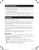
• Kit includes cable tester, crimping tool, LSA punchdown tool, and stripper
tool along with a carrying case
• RJ45, RJ11 and RJ12 cable tester combines a Main Tester unit with a
removable Remote Tester unit
• Tests cable connectivity, determining a connection, no connection, short
or open circuit, with LED lights indicating the type of connection
•
Features modes for fast and slow flashing of LEDs during automatic testing
16-07-119-9335F3-EN.indd 2 8/5/2016 9:48:43 AM