
Installation guide


LIGHTED LOWTOPPER - FIELD INSTALLATION GUIDE
2
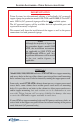
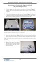
NOTE
Although the majority of figures in
this procedure depict a model 9100
ATM, the installation instructions
are applicable to 8100, 97XX and
RL5000 model ATMs as well. Any
significant differences will be noted
in the text and/or figures, as
applicable.
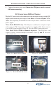
97XX Unitsl
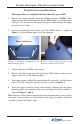
Model 8100, 9100, RL5000 and most 97XX ATMs have topper mounting
and access holes in the top of the cabinet, consisting of four small mounting
holes and one large access hole for internally routing the topper power cord.
Some early-model 97XX ATM cabinets do not possess a topper power cord
access hole; some cabinets have neither power cord access or mounting
holes: It is possible to cut holes in the cabinet to allow power cord access
and/or topper mounting, but such actions are to be undertaken at your
own risk! Triton Systems will accept no liability for damage that may
occur to the ATM and/or topper assembly in such cases.
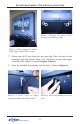
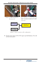
If your ATM has topper mounting holes and NO power cord access hole, an
access hole in the topper rear panel allows for external routing of the power
cord, if desired (AC powered only).
IMPORTANT NOTICE
Triton Systems has discontinued offering a ballast/bulb (AC-powered)
topper signage for production model 8100, 9100, and RL5000 (X-Scale/XP)
units. LED-lit (DC-powered) signage will be the only available option.
The AC-powered toppers will be available for field replaceable parts and
repair until inventory is depleted.
This manual will show the installation of the topper as well as the power
connections for both powered signage.