
Installation guide


LIGHTED LOWTOPPER - FIELD INSTALLATION GUIDE
3
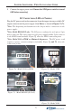
4. Remove the dome plugs from the top of the ATM cabinet to uncover the
topper cable access and mounting holes.
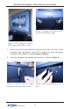
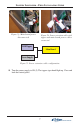
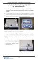
5. If the topper power cord will be routed internally (normally), feed the power
cord (AC or DC) into the large access hole, as shown in Figure 2.
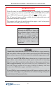
These procedures are completed with the terminal AC power OFF.
1. Remove the topper assembly from the shipping container. NOTE: If the
topper power cord will be routed outside the ATM cabinet, see the procedure
on Page 8 for instructions on routing the power cord through the topper
rear panel access hole.
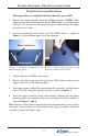
2. Locate the mounting holes on the top of the ATM cabinet, as shown in
Figure 1. Note that dome plugs cover the openings.
TOPPER INSTALLATION PROCEDURE
Figure 1. Location of topper access
and mounting holes.
Mounting Holes
Power Cord Access
3. Unlock and open the ATM control panel.
Figure 2. Feed topper power cord
through cabinet access hole.
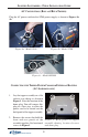
6. Place the topper assembly on top of the cabinet, ensuring that the topper
mounting studs are inserted into the corresponding holes in the cabinet, as
shown in Figures 3 and 4.
Note: Because of the slotted configuration of the mounting holes, there will be
some play (front-to-back) in the position of the topper assembly. Allow the
assembly to slide back until it stops.