
Installation guide


LIGHTED LOWTOPPER - FIELD INSTALLATION GUIDE
5
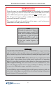
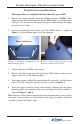
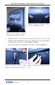
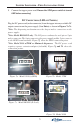
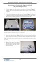
Plug the DC power cord (molex connector) from the topper into any available DC
output connector on the power supply (*see Notes) as shown in Figures 7a-7e.
1
Note: The dispensing mechanism uses the largest molex connection on the
power supply.
2
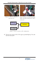
Note: Model RL5000XP only. The DC power cord may be an 8-pin or 2-pin
molex connector. The 8-pin connects to the power supply and the 2-pin connects
to the GPIO board assembly. Figure 7f show the GPIO connection point.
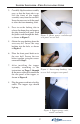
9. Connect the topper power cord. Ensure the ATM power switch is turned
OFF before connecting!
DC CONNECTIONS (LED-LIT TOPPER)
3
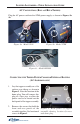
Note: Model 9100 w/TDM or Minimech dispensers. The DC power cord
requires a power extension adapter (included). Figure 7g and 7h show the
connection points.
Figure 7a. Model 9100 (w/SDD)
Figure 7b. Model 97XX
Figure 7c. Model RL5000 (X-Scale)
Figure 7d. Model 8100