
Installation guide


LIGHTED LOWTOPPER - FIELD INSTALLATION GUIDE
6
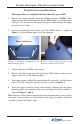
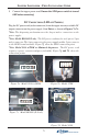
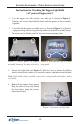
Figure 7e. Model RL5000 (XP)
GPIO assy
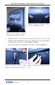
Figure 7f.
2
Note: Model RL5000 (XP)
3
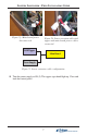
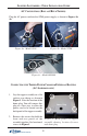
Note: 9100 w/TDM or Minimech - Locate the Power Extension cable (splitter)
included in kit (Figure below). The cables connectors are marked. Disconnect
the Main boards power input (Figure 7g) and connect to one leg of the extension
cable. Connect the toppers DC power cable to the other leg (Figure 7h).
Reconnect this power cable assembly back to the main board. Figure 7i shows
the power assembly diagram.
Power extension cable (splitter).