MODEL RL/FT5000XP PC-BASED ATMS USER MANUAL VERSION 2.0 TDN 07102-00057B Oct 23 2009 CORPORATE HEADQUARTERS: 21405 B Street Long Beach, MS 39560 Phone: (228) 575-3188 Fax: (228) 575-3200 COPYRIGHT NOTICE © 2008 Delaware Capital Formation, Inc. All Rights Reserved. Triton Systems of Delaware, Inc. is an operating company of Dover Electronics, Inc., a subsidiary of Dover Corporation (NYSE-DOV).
M ODEL RL/FT5000 XP U SER M ANUAL DISCLAIMER The manufacturer of the Automated Teller Machine (ATM) product(s) described herein makes no representations or warranties, either expressed or implied, by or with respect to anything in this manual, and shall not be liable for any implied warranties of fitness for a particular purpose or for any indirect, special, or consequential damages.
M ODEL RL/FT5000 XP U SER M ANUAL Harm to the Network: If the XP-series ATMs cause harm to the telephone network, the telephone company will notify the customer that a temporary discontinuation of service may be required. If advanced notice is not possible, the telephone company will notify the customer as soon as possible. You will be advised of your right to file a complaint with the FCC if you believe it’s necessary.
M ODEL RL/FT5000 XP U SER M ANUAL Before installing this equipment, users should ensure that it is permissible to be connected to the facilities of the local telecommunications company. The equipment must also be installed using an acceptable method of connection. The customer should be aware that compliance with the above conditions may not prevent degradation of service in some situations. Repairs to certified equipment should be coordinated by a representative designated by the supplier.
M ODEL RL/FT5000 XP U SER M ANUAL Les réparations de matériel homologué doivent être coordonnées par un représentant désigné par le fournisseur. L’entreprise de télécommunications peut demander à I’utilisateur de débrancher un appareil à la suite de réparations ou de modifications effectuées par l’utilisateur ou à cause de mauvais fonctionnement.
M ODEL RL/FT5000 XP U SER M ANUAL NOTE: This equipment has been tested and found to comply with the limits for a Class A digital device pursuant to Part 15 of FCC rules. These limits are designed to provide reasonable protection against harmful interference when the equipment is operated in a commercial environment.
M ODEL RL/FT5000 XP U SER M ANUAL NOTICES Copyright © Delaware Capital Formation, Inc., 2006. ALL RIGHTS RESERVED This publication is protected by copyright and all rights are reserved. No part of it may be reproduced or transmitted by any means or in any form, without prior consent in writing from Triton Systems of Delaware, Inc. The information in this publication has been carefully checked and is believed to be accurate. However, Triton Systems of Delaware, Inc.
M ODEL RL/FT5000 XP U SER M ANUAL WARRANTY STATEMENT Manufacturer warrants that the products delivered to a distributor will perform in accordance with the Manufacturer’s published specifications for thirteen months from date of shipment in Long Beach, MS. Manufacturer’s warranty shall not apply to any damage resulting from abuse, negligence, accident, or to any loss or damage to the products while in transit.
M ODEL RL/FT5000 XP U SER M ANUAL in any such action, provided the Manufacturer shall have had sole control of the defense of any such action and all negotiations for its settlement or compromise.
M ODEL RL/FT5000 XP U SER M ANUAL MODIFICATIONS These terms and conditions can be modified or rescinded only by writing signed by both the parties or their duly authorized agents. WAIVER INEFFECTIVE No claim or right arising out of or relating to a breach of these terms and conditions can be discharged in whole or in part by a waiver or renunciation of the claim or right unless the waiver or renunciation is supported by consideration and is in writing signed by the aggrieved party.
M ODEL RL/FT5000 XP U SER M ANUAL Limited Warranty covers normal use.
M ODEL RL/FT5000 XP U SER M ANUAL • If possible, call the shipping company before the driver leaves your delivery site. Make note of the damage on the “receipt of delivery” paperwork. If this is not possible, call them as soon as possible to report the damage. • Take photographs of the damaged packaging prior to opening the boxes. If this is not possible, make note of key points, such as whether the equipment is on a pallet, if the banding is intact, how the boxes are damaged, etc.
M ODEL RL/FT5000 XP U SER M ANUAL TRITON’S TECHNICAL SERVICES DEPARTMENT The primary purpose of the Technical Services department is to provide assistance to customers in the operation, trouble shooting, and repair of equipment manufactured by Triton. A toll-free phone number (1-800-259-6672) is provided for convenience. The Technical Services department operates to serve our customers. The staff is trained to follow our policies and procedures to ensure fair and uniform treatment of all our customers.
M ODEL RL/FT5000 XP U SER M ANUAL QUESTIONS ON OPERATION OF EQUIPMENT Technical support is available to owners of Triton equipment and to qualified service personnel. When calling for help with the configuration or operation of a Triton product, the caller must provide either positive identification as a service technician or the serial number of a Triton terminal. Technical support is provided during normal business hours for the life of the product.
M ODEL RL/FT5000 XP U SER M ANUAL CONTENTS SECTION 1 - INTRODUCTION ........................................................ 1 WHAT’S IN THIS MANUAL ................................................................................ 2 PC-BASED MODELS ......................................................................................... 2 CLASS OF SERVICE (BUSINESS-VS-LEVEL1) .......................................................... 2 OPERATING SYSTEM .......................................................
M ODEL RL/FT5000 XP U SER M ANUAL CONTENTS SECTION 4 - PREVENTATIVE MAINTENANCE .................................... 27 INTRODUCTION ................................................................................................. 28 REPLENISHING THE RECEIPT PAPER (MODEL RLXP) ............................................ 28 REPLENISHING THE RECEIPT PAPER (MODEL FTXP) ............................................ 31 REPLENISHING THE JOURNAL PRINTER (OPTIONAL) .............................................
M ODEL RL/FT5000 XP U SER M ANUAL CONTENTS KEYPAD .......................................................................................................... 71 KEYPAD DEVICE STATUS ............................................................................ 72 TEST KEYPAD .......................................................................................... 73 CLEAR TAMPER ........................................................................................ 74 RESET .................................
M ODEL RL/FT5000 XP U SER M ANUAL CONTENTS TERMINAL CONFIGURATION ............................................................................ 103 TERMINAL CONFIGURATION FUNCTIONS ............................................................. 106 GENERAL PARAMETERS .................................................................................... 107 TERMINAL NUMBER .................................................................................. 107 SEND CABINET ALARM STATUS ............................
M ODEL RL/FT5000 XP U SER M ANUAL CONTENTS PRINTER SETUP ................................................................................................ 124 GENERAL SETTINGS ................................................................................... 125 USE BLACK MARK PAPER .................................................................. 125 CONFIGURE - RECEIPT PRINT FORM / COUPON PRINT FORM ......................... 126 TEST - RECEIPT FORM SETTINGS / COUPON FORM SETTINGS .......................
M ODEL RL/FT5000 XP U SER M ANUAL CONTENTS SECTION 6 - ERROR CODES (WOSA / TERMINAL) ....................... 157 INTRODUCTION ................................................................................................. 158 NMD ERROR CODES ........................................................................................ 159 CARD READER ERROR CODES ........................................................................... 162 RECEIPT PRINTER ERROR CODES ..........................................
SECTION 1 INTRODUCTION 1
M ODEL RL/FT5000 XP U SER M ANUAL What’s in This Manual This manual describes the operating features of the RL/FT5000XP -series ATM family. The setup and operating procedures given in this manual are generally applicable to any RL5000XP or FT5000XP PC-based ATM. If your ATM does not have the ability to perform some of the features described in this manual, it is because your processor does not support the feature or the dispenser was purchased without that particular option.
INTRODUCTION Ope rating Sys te m Intel Celeron or optional Intel Pentium III Microsoft Windows XP Software options: Triton Standard - XFS Compliance - Emulation 40 GB 3.5" (89 mm) hard drive, expandable 256 MB SDRAM, expandable 10.4" (264 mm) SVGA color display with 800 x 600 resolution (FT5000XP) - optional sunlight viewable CD/DVD- ROM external drive, optional (FT5000XP) Rear Service Panel with 10.
M ODEL RL/FT5000 XP U SER M ANUAL Feature Highlights Important features of the RLXP/FTXP family are highlighted in the following list: One to four cassette friction feed multi-denomination dispensing mechanism. Front or rear delivery of banknotes and other value media such as tickets, stamps, phone cards, and vouchers. (Model FT5000XP) Rear Service Panel (RSP) with 10.4" SVGA color display and keyboard. Allows access to Management functions for security and ease of cassette loading and diagnostics.
INTRODUCTION FT5000XP RL5000XP STANDARD FEATURES Standard features of the XP-series ATMs are summarized in the following paragraphs. ACCESS AND TRANSACTION SECURITY Password-Controlled Access. Access to the ATM’s Management Functions is protected by a password-based access scheme. The ATM provides a “Master” password level of access and a flexible system of “User-level” passwords.
M ODEL RL/FT5000 XP U SER M ANUAL Encrypting PIN Pad (EPP) Entry Device Support Secure EPP entry device is an encryption system that offers additional protection for the customer PIN during entry at the ATM keypad. The EPP is compliant with all international encryption standards, Triple DES, and Visa® requirements. MULTIMEDIA INTERFACE (AUDIO/VIDEO) The ATM’s SVGA color display can display text and graphical content in a wide range of colors, providing an interesting and dynamic experience to the customer.
INTRODUCTION COMMUNICATIONS The XP-series ATMs support communication with the transaction processor using a variety of communications technologies. These include TCPIP, SNA/ SDLC, and BiSync. TCPIP (Ethernet) This method is used in applications where a central Local Area Network, or LAN, is used to connect multiple ATMs to a central server. The ATM can be treated as either a client or server on the network, while the server provides the interface to a transaction processing system.
M ODEL RL/FT5000 XP U SER M ANUAL MULTI-LANGUAGE SUPPORT The ATM has a screen language option. This option allows the terminal user to select a preferred language (such as Spanish or French) to conduct a transaction. MESSAGES These are informational messages that give important information to the customer before, during, and after a transaction. Messages can be locally customized to meet local requirements.
SECTION 2 BASIC OPERATION 9
M ODEL RL/FT5000 XP U SER MANUAL INTRODUCTION This section describes the basic operation of the terminal. The following topics are covered: 1. Control Panel Layout. Describes the layout of the terminal’s control panel. 2. Keypad Operation. Describes the use of the alphanumeric keypads. 3. Screen Function Keys. Describes the use of the screen keys. 4. Rear Service Panel. 5. Menu-Based Operation. Provides a general overview of the terminal display interface. 6. Accessing Management Functions.
BASIC OPERATION Menu keys LCD screen Receipt chute Card reader Main keypad Headphone jack Fig. 2-1b. Control panel layout (FTXP) KEYPAD OPERATION See Figure 2-2 and Table 2-1. The main keypad consists of 10 alphanumeric keys, two arrow keys and four large control keys, all located in a 16-key group beneath the LCD display. The table lists the keys and their functions. The keypad has integral raised Braille symbols to conform to the requirements of the Americans with Disabilities Act. CTRL key Fig.
M ODEL RL/FT5000 XP U SER MANUAL TABLE 2-1 - FRONT KEYBOARD MAP K EY KEYBOARD MAP Left Arrow Left Arrow or Up Arrow Right Arrow Right Arrow or Dow n Arrow Enter Enter C an cel E scap e Clear TAB C T R L K ey (Blank Key) S p ace 0-9 0-9 ACTION - Scroll Back in Current Field (for Combo and Edit Boxes). - Change focus to the previous control. - Moves up in a list control. - Scroll Forw ard in Current Field (for Combo and Edit Boxes). - Change focus to the next control.
BASIC OPERATION REAR SERVICE PANEL (MODEL FTXP) The Rear Service Panel (RSP) houses a 10.4" (264mm) SVGA color display with 800 x 600 resolution and a keyboard with mouse pad. This provides convenient user-access to most Management functions from inside the facility. The assembly also pivots out allowing access to the PC assembly, power supply, and optional printer assembly. Figure 2-4. Rear service panel (display/keyboard).
M ODEL RL/FT5000 XP U SER MANUAL MENU-BASED OPERATION The terminal operates as a menu driven system. Messages and menu options presented on the LCD display screen guide the user’s actions. The desired menu option is selected by pressing one of the screen keys located to the left and right of the display. For the purpose of security, many screens timeout after a preset time interval, usually 30 seconds. The timeout length may vary depending on the function being performed.
BASIC OPERATION VOICE-ENABLED TRANSACTIONS The terminal provides voice feedback via an integrated output jack, enabling sight-impaired users to plug in a set of headphones and receive spoken instructions to assist them in using the ATM. Figure 2-6, headphone jack location, shows the location of the headphone jack on the RL5000XP. Fig. 2-6. Headphone jack location. Raised symbols helps a user locate the headphone jack.
M ODEL RL/FT5000 XP U SER MANUAL THIS PAGE INTENTIONALLY LEFT BLANK 16
SECTION 3 REPLENISHING CASSETTES 17
M ODEL RL/FT5000 XP U SER MANUAL INTRODUCTION The purpose of this section of the manual is to describe the procedures for: (1) removing and replacing note cassettes, (2) loading cassettes, and (3) removing and replacing the reject notes (as applicable). Information concerning note handling and quality issues are explained where appropriate. The mechanism is able to reject single notes or bundles. A bundle reject occurs when more than one note is rejected at the same time.
REPLENISHING CASSETTES USED NOTE DEFECTS Remove foreign objects (e.g. pins, paper clips, crumbs, etc.). Adhesive or “sticky” substances on the surface of the paper. Remove torn or very worn notes. Straighten any folded notes. Tears extending more than 1/2” from the edge of the currency. Tears, holes, or missing sections in the body of the currency. Tape on the surface of the currency used for repairing, patching or any other purpose. Staples, pins, or any other foreign body attached to the notes.
M ODEL RL/FT5000 XP U SER MANUAL REPLENISHING CASSETTES To perform a cash replenishment, enter Management Functions > Terminal Settlement Functions > Replenish Cassette(s). Follow the prompts to , load cassettes, and cassettes. REMOVING NOTE CASSETTES 1. Open the electronic lock on the security container door and open the door to gain access to the dispensing mechanism. 2.
REPLENISHING CASSETTES OPENING NOTE CASSETTES 1. Insert the key into the cassette lock (Figure 4-5). To unlock the cassette, apply inward pressure on the key while turning it clockwise to the stop position (approximately a quarter-turn). Open the cassette by simultaneously pressing the release button and lifting the lid. Flip the lid back fully, allowing it to rest on the table or other flat surface (Figure 4-6). Figure 4-6. Release button. Figure 4-5. Key inserted. 2.
M ODEL RL/FT5000 XP U SER MANUAL LOADING NOTE CASSETTES 1. • Load the cassette with currency. The shape of some notes may be affected by conditions of storage or bundling, preventing them from forming neat even piles. If not corrected, such conditions may cause notes to be rejected by the dispensing mechanism. To compensate for the most common conditions of slanting or cupped note piles, follow the directions given here. Notes with no apparent shape problems are referred to as “common” notes.
REPLENISHING CASSETTES 3. Move the pusher plate against the notes with just enough pressure to hold the notes in the correct position when closing the lid and inserting the cassette into the mechanism (Figure 4-11). 4. Move the white plastic levers (Pawls) on the pusher plate to their fully extended position. This will allow the pusher plate to retract and release pressure from the note stack when an unlock command is sent to the dispenser (Fig. 4-12). Figure 4-11. Moving pusher plate against notes. 5.
M ODEL RL/FT5000 XP U SER MANUAL REMOVING THE REJECT CASSETTE *IMPORTANT* If you remove the reject vault with power applied, the terminal will sense this and automatically reset the rejected note count to ZERO. Therefore, to ensure an accurate rejected note count NEVER REMOVE THE REJECT VAULT WITH POWER APPLIED WITHOUT CHECKING FOR AND REMOVING ANY REJECTED NOTES! 1. Ensure cassettes are .
REPLENISHING CASSETTES 2. The reject cassette is now open for collecting any rejected bundle notes. These will be present in the folding tray. After retrieving any rejected bundle notes, lift the folding tray and check underneath for any rejected single notes (Figures 4-17 and 4-18). 3. After removing any rejected notes, close the lid. Fold the lid down to its locked position. The release button should “pop” out, allowing the lid to mate cleanly with the body of the cassette.
M ODEL RL/FT5000 XP U SER MANUAL VERIFY OPERATION 1. Close and lock the security cabinet. 2. Verify the cassettes are in the dispenser. 3. In Management Functions, select DIAGNOSTICS, then CASH DISPENSER. 4. Select the TEST DISPENSE option. Enter # of notes to be dispensed (1-5) from the individual cassettes that are installed (“A”, “B”, “C”,or “D”). Select PERFORM TEST. The Test Dispense operation will start. Figure 4-19. Enter # of notes. 5.
SECTION 4 PREVENTATIVE MAINTENANCE 27
M ODEL RL/FT5000 XP U SER M ANUAL INTRODUCTION REPLENISHING RECEIPT PAPER (RL5000XP) This section of the manual covers preventive and corrective maintenance procedures appropriate for user personnel. The following areas are covered: 1. R EPLENISHING P APER RL/FT XP (RECEIPT PRINTER). Describes how to replace a spent receipt paper roll. 2. R EPLENISHING P APER (J OURNAL P RINTER ). Describes how to replace the spent journal paper roll.
PREVENTATIVE MAINTENANCE 3. Press and hold the paper feed button until the paper clears the front of the printer. Paper feed button ** CAUTION ** Do not pull the paper backward through the printer. This may leave paper fragments that can cause paper jams. 4. Remove the existing paper roll or empty spindle (as appropriate) from the paper support bracket. 5. Unwind about 18 inches from the end of the new roll of paper. Using scissors, cut off the excess.
M ODEL RL/FT5000 XP U SER M ANUAL 8. If the paper is not automatically taken-up by the printer, check the tension roller lever on the printer chassis. Pull the pin located on the right side of the printer bracket shown. Rotate the assembly towards the front of the control panel. 9. The blue tension lever is located on the left side. It must be in the closed position (blue lever facing towards the right). If not, just move the lever (moves in 3 positions) to the correct position.
PREVENTATIVE MAINTENANCE REPLENISHING RECEIPT PAPER (FT5000XP) * NOTE * NOTE: This operation must be completed with the AC power applied to the ATM. 1. Open the left side service panel on the cabinet sleeve. 2. If paper remains on the roll, cut the paper between the roll and the input to the printer with a pair of scissors. 3. Triton recommends the use of 20# thermal printer paper (Triton P/N 05403-00053). This receipt paper has been shown to improve performance and reliability.
M ODEL RL/FT5000 XP U SER M ANUAL 7. Insert the edge of the paper roll into the printer take-up slot.The printer will automatically grip and pull the paper into the paper path. If the paper feeds automatically, skip to Step 10. If the paper does not feed automatically, continue with Step 8. 8. If the paper is not automatically taken-up by the printer, check the tension roller lever on the printer chassis. Grasp the handle shown and lift up. Pivot assembly down until assembly is fully open. 9.
PREVENTATIVE MAINTENANCE REPLENISHING PAPER (JOURNAL PRINTER) *** Warning *** Remove power from the Journal Printer during any servicing that requires the user to insert fingers into the printer wheel area. NOTE: The following steps reference Figure 6-1 and 6-2. Cut / Feed switch Paper “out’ sensor Bail Power switch Bail slot Figure 6-1. Journal printer. 1. Access the journal printer and turn the power switch OFF. 2. Lift the Bail (item 3) and remove any paper that may be inside the printer.
M ODEL RL/FT5000 XP U SER M ANUAL Figure 6-2. Loading journal paper. 4. Direct the paper (item 6) from the paper roll (item 4) through the Paper Out Sensor and down into the Guide slot (item 7) until the paper stops against the Feed Mechanism (item 8). Remove the Journal Take-up Carriage (item 9). 5. The paper is now ready to be advanced automatically through the rest of the printer assembly. First, turn the power switch ON.
PREVENTATIVE MAINTENANCE LOADING INK CARTRIDGE (JOURNAL PRINTER) NOTE: The following steps reference Figures 6-3 through 6-6. Cut / Feed switch Paper “out’ sensor Bail Power switch Bail slot Figure 6-3. Journal printer. 1. Access the journal printer and turn the power switch OFF. 2. If there is a used ink cartridge already loaded, remove it by opening the Bail and pulling the cartridge directly off the Drive shaft (Figure 6-4).
M ODEL RL/FT5000 XP U SER M ANUAL 3. Before inserting the new ink cartridge, turn the cartridge knob “counterclockwise” until ribbon is taut (Figure 6-5). 4. Open the Bail. Carefully mount the ink cartridge onto the drive shaft, keeping the ribbon between the Platen and the Printhead (Figure 6-6). Knob Figure 6-5. Turn knob counterclockwise. 5.
PREVENTATIVE MAINTENANCE CLEANING THE ENCLOSURE CARD READER CLEANING The ATM front panel/trim is highly durable, resisting scratches and finger smudges. However, occasional cleaning of the front panel and the plastic enclosure may be desirable. A soft dry or slightly damp cloth may be used for cleaning. For best results, use a weak solution of a mild detergent and water. Special cleaning cards (P/N 0620000055) are available for proper maintenance of the card reader.
M ODEL RL/FT5000 XP U SER M ANUAL THIS PAGE INTENTIONALLY LEFT BLANK 38
SECTION 5 MANAGEMENT FUNCTIONS 39
M ODEL RL/FT5000 XP U SER M ANUAL INTRODUCTION This section describes the Management Functions available running Prism 912 emulation controlling the ATM. WHAT IS PRISM 912-EMULATION? Prism offers true, open-ended, object-oriented architecture using industry standard Microsoft® development tools. The unique software design and integrated Web browser enables Prism to be plug compatible with existing ATM processor networks without changes to the existing host system.
MANAGEMENT FUNCTIONS • Prism allows the FI to convert 912 screens into HTML format obviating any additional resource burden or vendors’ Professional Services intervention. · Prism is multi-vendor capable. WHAT IS MEANT BY A “WINDOWS-BASED” ATM? The current ATM environment is still one that is largely driven in a Diebold® or NCR® emulation environment that uses traditional “states and screens” – command sets.
M ODEL RL/FT5000 XP U SER M ANUAL XP PRISM SOFTWARE ARCHITECTURE The above diagram is a high level overview of the Triton ATM software architecture running Prism. The base operating system is Windows XP Pro and at the low end you have hardware devices with their firmware that communicate to the WOSA middleware developed by KAL. Prism application conforms to WOSAXFS standards. WOSA-XFS allows higher-level applications to communicate with low-level device drivers.
MANAGEMENT FUNCTIONS Prism 912-emulation is based on Diebold® iSeries 912 message standard.
M ODEL RL/FT5000 XP U SER M ANUAL DISPLAY POWER -UP SEQUENCE When the ATM is powered on, or has been re-booted, “Out of Service” is displayed on the front screen. The rear screen (FTXP model) will display the “ATM Status” screen. After the power-up sequence is complete, the “ATM Startup Options” screen will be displayed on the front LCD of the RLXP. On the FTXP, the startup option will be displayed on the rear LCD - the front LCD will display the “Out of Service” screen. Figure 5-1.
MANAGEMENT FUNCTIONS Figure 5-2. Enter your Master or User password. You must enter an appropriate password in the dialog box that appears when the Management Functions option is selected. The password will consist of a 2-digit ID code and a password of 4-12 digits; for example, 051234 could be a password entry consisting of an ID code of 05 and a password of 1234. Â Â Enter the 2-digit ID code, then press . Enter your password and press again.
M ODEL RL/FT5000 XP U SER M ANUAL SWITCHING SCREENS (MODEL FTXP) The FTXP has two (2) displays - the front (Customer side) and rear (Operator service side). You can access all menu options in the Management functions from the front display. When accessing Management functions from the rear display, certain options (Key Management) will need to be configured from the front display. You will be prompted to switch screens when this occurs (Figure 5-4). Figure 5-4. Switch screen prompt.
MANAGEMENT FUNCTIONS FUNCTION AVAILABILITY Once you have entered the Main Menu, you may perform any of the functions allowed by the type of password used (access level). Each Main Menu option description will include the function name, instructions for accessing the function, a description of the function, and any associated factory default values. The Main Menu screen allows the service provider/terminal operator to access the following Management functions: 1. Terminal Settlement Functions.
M ODEL RL/FT5000 XP U SER M ANUAL Management Reports Many Management Functions, such as Terminal Settlement, Journal, and Diagnostic functions, produce a report summarizing the results of the operation. Most reports are displayed in a Management Report dialog, which you can use to print the report to the receipt printer or save to an external memory device. The buttons on the Management Report dialog let you perform the following actions: (Figure 5-5) 4. Page Up.
MANAGEMENT FUNCTIONS TERMINAL SETTLEMENT FUNCTIONS TERMINAL SETTLEMENT FUNCTIONS TERMINAL SETTLEMENT FUNCTIONS MENU OPTIONS ..................... 50 VIEW ATM SETTLEMENT TOTALS ................................................. 51 CLEAR ATM SETTLEMENT TOTALS ............................................... 52 REPLENISH CASSETTE(S) ..............................................................
M ODEL RL/FT5000 XP U SER M ANUAL TERMINAL SETTLEMENT FUNCTIONS ACCESS INSTRUCTIONS: 1. From the MAIN MENU screen, select the TERMINAL SETTLEMENT FUNCoption by pressing number <1> on the keypad. TIONS DESCRIPTION: The TERMINAL SETTLEMENT FUNCTIONS option allows the terminal operator to perform the following functions: 1. VIEW ATM SETTLEMENT TOTALS. Displays the total number of captured cards and dispensed currency with start/end dates. 2. CLEAR ATM SETTLEMENT TOTALS.
MANAGEMENT FUNCTIONS VIEW ATM SETTLEMENT TOTALS ACCESS INSTRUCTIONS: 1. From the TERMINAL SETTLEMENT FUNCTIONS screen, select the VIEW ATM SETTLEMENT TOTALS option by pressing number <1> on the keypad. DESCRIPTION: The VIEW ATM SETTLEMENT TOTALS function displays the total number of captured cards and dispensed currency with the start and end dates. The start date is the last ATM settlement reset day and the end date is the current date.
M ODEL RL/FT5000 XP U SER M ANUAL CLEAR ATM SETTLEMENT TOTALS ACCESS INSTRUCTIONS: 1. From the TERMINAL SETTLEMENT FUNCTIONS screen, select the CLEAR ATM SETTLEMENT TOTALS option by pressing number <2> on the keypad. DESCRIPTION: The CLEAR ATM SETTLEMENT TOTALS function resets all the ATM settlement totals to zero (0) and resets the start date to the current date/time. Press the number <1> on the keypad to clear the ATM settlement totals or number <2> to exit without clearing.
MANAGEMENT FUNCTIONS REPLENISH CASSETTE(S) ACCESS INSTRUCTIONS: 1. From the TERMINAL SETTLEMENT FUNCTIONS screen, select the REPLENISH CASSETTE(S) option by pressing number <3> on the keypad. DESCRIPTION: This function allows user to unlock/lock the cassette(s) for currency replenishment. During replenishment: Â A screen warning appears that the time out function normally associated with the Management Functions is disabled. Press <1> to continue. Â Wait for all cassettes to be unlocked.
M ODEL RL/FT5000 XP U SER M ANUAL DIAGNOSTICS DIAGNOSTICS DIAGNOSTICS MENU OPTIONS .................................................... 56 CASH DISPENSER ........................................................................ 57 CASH DISPENSER STATUS ........................................................................... 58 PURGE ..................................................................................................... 59 TEST DISPENSE ......................................................
MANAGEMENT FUNCTIONS PRINTER ...................................................................................... 68 DEVICE STATUS ......................................................................................... 69 PRINT TEST DATA ..................................................................................... 70 RESET ...................................................................................................... 70 KEYPAD .............................................................
M ODEL RL/FT5000 XP U SER M ANUAL DIAGNOSTICS ACCESS INSTRUCTIONS: 1. From the MAIN MENU screen, select the DIAGNOSTICS option by pressing number <2> on the keypad. DESCRIPTION: The DIAGNOSTICS option allows the terminal operator to perform the following functions: 1. CASH DISPENSER. testing functions. Displays a menu of dispenser status reporting and 2. CARD READER. Displays a menu of card reader device status and test functions. 3. PRINTER.
MANAGEMENT FUNCTIONS CASH DISPENSER ACCESS INSTRUCTIONS: 1. From the DIAGNOSTICS screen, select the CASH DISPENSER option by pressing number <1> on the keypad. DESCRIPTION: The following options will be available from the CASH DISPENSER screen: 1. CASH DISPENSER STATUS. Displays a Management Report showing current dispenser hardware status. 2. PURGE. Performs a purge operation on the dispenser. 3. TEST DISPENSE.
M ODEL RL/FT5000 XP U SER M ANUAL CASH DISPENSER STATUS ACCESS INSTRUCTIONS: 1. From the DIAGNOSTICS screen, select the CASH DISPENSER option by pressing number <1> on the keypad. 2. From the CASH DISPENSER screen, select the CASH DISPENSER STATUS option by pressing number <1> on the keypad. DESCRIPTION: The CASH DISPENSER STATUS report identifies the type of dispensing mechanism installed and shows the results of the most recent dispenser status check.
MANAGEMENT FUNCTIONS PURGE ACCESS INSTRUCTIONS: 1. From the DIAGNOSTICS screen, select the CASH DISPENSER option by pressing number <1> on the keypad. 2. From the CASH DISPENSER screen, select the PURGE option by pressing number <2> on the keypad. DESCRIPTION: The PURGE command allows the user to instruct the dispenser to remove all documents from the feed path.
M ODEL RL/FT5000 XP U SER M ANUAL TEST DISPENSE ACCESS INSTRUCTIONS: 1. From the DIAGNOSTICS screen, select the CASH DISPENSER option by pressing number <1> on the keypad. 2. From the CASH DISPENSER screen, select the TEST DISPENSE option by pressing number <3> on the keypad. DESCRIPTION: The TEST DISPENSE command allows the user to dispense note(s) from each installed and operational cassette into the reject cassette. This test exercises the dispenser mechanism without sending notes to the exit.
MANAGEMENT FUNCTIONS FORCE UNLOCK Cassette ACCESS INSTRUCTIONS: 1. From the DIAGNOSTICS screen, select the CASH DISPENSER option by pressing number <1> on the keypad. 2. From the CASH DISPENSER screen, select the FORCE UNLOCK CASSETTE option by pressing number <4> on the keypad. DESCRIPTION: The FORCE UNLOCK CASSETTE function provides a means of overriding the unlocking mechanism associated with a specific cassette. It is only to be used immediately after failure of a normal cassette unlock operation.
M ODEL RL/FT5000 XP U SER M ANUAL INJECT NEW CASSETTE ID ACCESS INSTRUCTIONS: 1. From the DIAGNOSTICS screen, select the CASH DISPENSER option by pressing number <1> on the keypad. 2. From the CASH DISPENSER screen, select the INJECT NEW CASSETTE ID option by pressing number <5> on the keypad. DESCRIPTION: The NMD-100 dispensing mechanism use cassettes that possess onboard memory. This memory enables a cassette to store its own identification (ID) code.
MANAGEMENT FUNCTIONS UNLOCK / LOCK ALL CASSETTES ACCESS INSTRUCTIONS: 1. From the DIAGNOSTICS screen, select the CASH DISPENSER option by pressing number <1> on the keypad. 2. From the CASH DISPENSER screen, select the UNLOCK ALL CASSETTES option by pressing number <6> on the keypad. 3. From the CASH DISPENSER screen, select the LOCK ALL CASSETTES option by pressing number <7> on the keypad.
M ODEL RL/FT5000 XP U SER M ANUAL CARD READER ACCESS INSTRUCTIONS: 1. From the DIAGNOSTICS screen, select the CARD READER option by pressing number <2> on the keypad. DESCRIPTION: The CARD READER option allows the terminal operator to perform the following functions: 1. CARD READER STATUS. Displays a management report showing card reader hardware status. 2. SCAN CARD. Tests/scans cards and provides card information. 3. TRACK 3 READ / WRITE. Verifies that data can be written to Track 3. 4. RESET.
MANAGEMENT FUNCTIONS CARD READER STATUS ACCESS INSTRUCTIONS: 1. From the DIAGNOSTICS screen, select the CARD READER option by pressing number <2> on the keypad. 2. From the CARD READER screen, select the CARD READER STATUS option by pressing number <1> on the keypad. DESCRIPTION: The CARD READER STATUS displays a report showing the card reader hardware status. It shows the card reader type, firmware version, SP version, and device status.
M ODEL RL/FT5000 XP U SER M ANUAL SCAN CARD ACCESS INSTRUCTIONS: 1. From the DIAGNOSTICS screen, select the CARD READER option by pressing number <2> on the keypad. 2. From the CARD READER screen, select the SCAN CARD option by pressing number <2> on the keypad. DESCRIPTION: The SCAN CARD function reports the number of tracks the card reader is able to scan. It prompts you to insert and remove a card. Upon removing the card, a management report dialog is displayed.
MANAGEMENT FUNCTIONS T RACK 3 READ/WRITE ACCESS INSTRUCTIONS: 1. From the DIAGNOSTICS screen, select the CARD READER option by pressing number <2> on the keypad. 2. From the CARD READER screen, select the TRACK 3 READ/WRITE option by pressing number <3> on the keypad. DESCRIPTION: The TRACK 3 READ / WRITE function reads and retains existing Track 3 data, writes a specific data pattern to track 3, reads and verifies the data pattern written, and restores (writes) the original track 3 data to the card.
M ODEL RL/FT5000 XP U SER M ANUAL PRINTER ACCESS INSTRUCTIONS: 1. From the DIAGNOSTICS screen, select the PRINTER option by pressing number <3> on the keypad. DESCRIPTION: The PRINTER option allows the terminal operator to perform the following functions: 1. DEVICE STATUS. Displays a management report that shows properties of the terminal printer, such as printer name, assigned port, driver version, and printer resolution. 2. PRINT TEST DATA. Allows user to perform an operational test of the printer.
MANAGEMENT FUNCTIONS DEVICE STATUS ACCESS INSTRUCTIONS: 1. From the DIAGNOSTICS screen, select the PRINTER option by pressing number <3> on the keypad. 2. From the PRINTER screen, select the DEVICE STATUS option by pressing number <1> on the keypad.
M ODEL RL/FT5000 XP U SER M ANUAL PRINT TEST DATA ACCESS INSTRUCTIONS: 1. From the DIAGNOSTICS screen, select the PRINTER option by pressing number <3> on the keypad. 2. From the PRINTER screen, select the PRINT TEST DATA option by pressing number <2> on the keypad. DESCRIPTION: The PRINT TEST DATA function re-initializes and then performs an operational test of the printer.
MANAGEMENT FUNCTIONS KEYPAD ACCESS INSTRUCTIONS: 1. From the DIAGNOSTICS screen, select the KEYPAD option by pressing number <4> on the keypad. DESCRIPTION: The KEYPAD option allows the terminal operator to perform the following functions: 1. KEYPAD DEVICE STATUS. Displays a management report that shows information such as keypad status, serial number, version number, and loaded encrypted key information. 2. TEST KEYPAD. Displays a dialog box showing the state (down/up) of any keypad button. 3.
M ODEL RL/FT5000 XP U SER M ANUAL KEYPAD DEVICE STATUS ACCESS INSTRUCTIONS: 1. From the DIAGNOSTICS screen, select the KEYPAD option by pressing number <4> on the keypad. 2. From the KEYPAD screen, select the KEYPAD DEVICE STATUS option by pressing number <1> on the keypad. DESCRIPTION: The KEYPAD DEVICE STATUS function displays a report that shows the current operational status of the keypad device.
MANAGEMENT FUNCTIONS TEST KEYPAD ACCESS INSTRUCTIONS: 1. From the DIAGNOSTICS screen, select the KEYPAD option by pressing number <4> on the keypad. 2. From the KEYPAD screen, select the TEST KEYPAD option by pressing number <2> on the keypad. DESCRIPTION: The TEST KEYPAD function enables you to verify proper operation of the numeric, function, and control buttons of the terminal. Press any button (except the button) and the report dialog will indicate the state of the button (ie; Pressed).
M ODEL RL/FT5000 XP U SER M ANUAL CLEAR TAMPER ACCESS INSTRUCTIONS: 1. From the DIAGNOSTICS screen, select the KEYPAD option by pressing number <4> on the keypad. 2. From the KEYPAD screen, select the CLEAR TAMPER option by pressing number <3> on the keypad. DESCRIPTION: The CLEAR TAMPER function enables you to reset a tamper condition of the encrypting PIN pad if one exists.
MANAGEMENT FUNCTIONS GENERAL I/O DIAGNOSTICS ACCESS INSTRUCTIONS: 1. From the DIAGNOSTICS screen, select the GENERAL I/O DIAGNOSTICS option by pressing number <5> on the keypad. DESCRIPTION: The GENERAL I/O DIAGNOSTICS option allows the terminal operator to perform the following functions: 1. LED INDICATORS. When selected, this function will flash all LEDs for 5 seconds.
M ODEL RL/FT5000 XP U SER M ANUAL 2. HEADPHONE TEST. This option reports whether the headphones can be detected (inserted or removed). This status is displayed in a management report dialog which you can print to the receipt printer or save to an external memory device. NOTE (Model FT5000XP): This option can only be performed from the front operator panel. 3. SAFE DOOR TEST. Allows user to test safe door switch. The management report displays open/closed conditions.
MANAGEMENT FUNCTIONS 4. CABINET DOOR TEST. Allows user to test cabinet door switches. The management report displays open/closed conditions. When the “Cabinet Door Test” is selected from the Diagnostics menu at the front LCD (FT XP ), the general acknowledgement dialog screen appears and directs a user to switch the screen to the rear LCD. This status is displayed in a management report dialog which you can print to the receipt printer or save to an external memory device. 5. PRINTER POSITION TEST.
M ODEL RL/FT5000 XP U SER M ANUAL ELECTRONIC JOURNAL ELECTRONIC JOURNAL ELECTRONIC JOURNAL MENU OPTIONS ....................................... 79 EXPORT UNAUDITED RECORDS .................................................... 80 DISPLAY LAST X RECORDS ......................................................... 81 JOURNAL STATISTICS ................................................................... 82 JOURNAL SETTINGS ..................................................................... 83 AUTO EXPORT ......
MANAGEMENT FUNCTIONS ELECTRONIC JOURNAL ACCESS INSTRUCTIONS: 1. From the MAIN MENU screen, select the ELECTRONIC JOURNAL option by pressing number <3> on the keypad. DESCRIPTION: The ELECTRIC JOURNAL option allows the terminal operator to perform the following functions: 1. EXPORT UNAUDITED RECORDS. This function is used to save all unaudited records in the electronic journal to an external storage device. 2. DISPLAY LAST X RECORDS.
M ODEL RL/FT5000 XP U SER M ANUAL EXPORT UNAUDITED RECORDS ACCESS INSTRUCTIONS: 1. From the MAIN MENU screen, select the ELECTRONIC JOURNAL option by pressing number <3> on the keypad. 2. From the ELECTRONIC JOURNAL screen, select the EXPORT UNAUDITED RECORDS option by pressing the number <1> on the keypad. DESCRIPTION: The EXPORT UNAUDITED RECORDS function allows user to save all unaudited records to an external storage device that is attached to any available USB port on the computer.
MANAGEMENT FUNCTIONS DISPLAY LAST X RECORDS ACCESS INSTRUCTIONS: 1. From the MAIN MENU screen, select the ELECTRONIC JOURNAL option by pressing number <3> on the keypad. 2. From the ELECTRONIC JOURNAL screen, select the DISPLAY LAST X RECORDS option by pressing the number <2> on the keypad. DESCRIPTION: The DISPLAY LAST X RECORDS function is used to display and print records from the electronic journal, either before or after they have been audited.
M ODEL RL/FT5000 XP U SER M ANUAL JOURNAL STATISTICS ACCESS INSTRUCTIONS: 1. From the MAIN MENU screen, select the ELECTRONIC JOURNAL option by pressing number <3> on the keypad. 2. From the ELECTRONIC JOURNAL screen, select the JOURNAL STATISTICS option by pressing the number <3> on the keypad.
MANAGEMENT FUNCTIONS JOURNAL SETTINGS ACCESS INSTRUCTIONS: 1. From the MAIN MENU screen, select the ELECTRONIC JOURNAL option by pressing number <3> on the keypad. 2. From the ELECTRONIC JOURNAL screen, select the JOURNAL SETTINGS option by pressing the number <4> on the keypad. DESCRIPTION: The JOURNAL SETTINGS function sets the parameters that will allow the electronic journal data to be exported or deleted at a predefined schedule based on the time in days and age of the records.
M ODEL RL/FT5000 XP U SER M ANUAL 3. DELETE INTERVAL (DAYS). If Auto Delete is enabled, allows user to set (in days) how often the delete function will be performed. The default value is ‘7’. 4. DELETE RECORDS OLDER THAN (DAYS). If Auto Delete is enabled, allows user to set (in days) the deletion of journal records older than the specified number of days. The default value is ‘91’. 5. SAVE SETTINGS/EXIT.
MANAGEMENT FUNCTIONS PASSWORD MAINTENANCE PASSWORD MAINTENANCE PASSWORD MAINTENANCE MENU OPTIONS ................................. 86 CHANGE USER PASSWORD .......................................................... 87 CHANGE USER NAME .................................................................. 88 MODIFY USER ACCESS ....................................................... 89 - 91 ADD USER .................................................................................. 92 REMOVE USER ................
M ODEL RL/FT5000 XP U SER M ANUAL PASSWORD MAINTENANCE ACCESS INSTRUCTIONS: 1. From the MAIN MENU screen, select the PASSWORD MAINTENANCE option by pressing number <4> on the keypad. DESCRIPTION: The PASSWORD MAINTENANCE option allows the terminal operator to perform the following functions: Note: Functions with astericks (*) can only be performed by the Master user. 1. CHANGE USER PASSWORD. Use this function to change the currently logged in user’s password. 2. CHANGE USER NAME.
MANAGEMENT FUNCTIONS CHANGE USER PASSWORD ACCESS INSTRUCTIONS: 1. From the MAIN MENU screen, select the PASSWORD MAINTENANCE option by pressing number <4> on the keypad. 2. From the PASSWORD MAINTENANCE screen, select the CHANGE USER PASSWORD option by pressing number <1> on the keypad. DESCRIPTION: The CHANGE USER PASSWORD function allows the currently logged in user to change their password. To change the password: Â Select <1> on the keypad.
M ODEL RL/FT5000 XP U SER M ANUAL CHANGE USER NAME ACCESS INSTRUCTIONS: 1. From the MAIN MENU screen, select the PASSWORD MAINTENANCE option by pressing number <4> on the keypad. 2. From the Password Maintenance screen, select the CHANGE USER NAME option by pressing number <2> on the keypad. DESCRIPTION: The CHANGE USER NAME function allows the currently logged in user to change their user name. To change the user name: Â Select <1> on the keypad.
MANAGEMENT FUNCTIONS MODIFY USER ACCESS ACCESS INSTRUCTIONS: 1. From the MAIN MENU screen, select the PASSWORD MAINTENANCE option by pressing number <4> on the keypad. 2. From the PASSWORD MAINTENANCE screen, select the MODIFY USER ACCESS option by pressing number <3> on the keypad. * Note * This function is only available to personnel with Master password access to Management Functions.
M ODEL RL/FT5000 XP U SER M ANUAL  Front Keypad. Use the left and right arrow (< >) keys to move the highlight bar up and down the list. È) and up (Ç Ç) keys to move the highlight  Rear PC Keypad. Use down (È bar up and down the list. 1. To deselect ALL the functions within a group, highlight the function group name and press the key. ALL the functions within that group will be deselected (checkmarks removed) indicating that access to those functions will be denied.
MANAGEMENT FUNCTIONS 2. To select ALL the functions within a group, highlight the function group name and press the key. ALL the functions within that group will be selected (checkmarks added) indicating that access to those functions will be allowed. 3. To deselect SPECIFIC functions within a group, highlight the specific function and press the key. That function will be deselected (checkmark removed) indicating that access to that function will be denied. 4.
M ODEL RL/FT5000 XP U SER M ANUAL ADD USER ACCESS INSTRUCTIONS: 1. From the MAIN MENU screen, select the PASSWORD MAINTENANCE option by pressing number <4> on the keypad. 2. From the PASSWORD MAINTENANCE screen, select the ADD USER option by pressing number <4> on the keypad. * Note * This function is only available to personnel with Master password access to Management Functions. DESCRIPTION: The ADD USER function allows adding a new user to the system. To add a new user: Â Select <1> on the keypad.
MANAGEMENT FUNCTIONS REMOVE USER ACCESS INSTRUCTIONS: 1. From the MAIN MENU screen, select the PASSWORD MAINTENANCE option by pressing number <4> on the keypad. 2. From the PASSWORD MAINTENANCE screen, select the REMOVE USER option by pressing number <5> on the keypad. * Note * This function is only available to personnel with Master password access to Management Functions. DESCRIPTION: The REMOVE USER function allows removing an existing user from the system.
M ODEL RL/FT5000 XP U SER M ANUAL TERMINAL USERS ACCESS INSTRUCTIONS: 1. From the MAIN MENU screen, select the PASSWORD MAINTENANCE option by pressing number <4> on the keypad. 2. From the PASSWORD MAINTENANCE screen, select the TERMINAL USERS option by pressing number <6> on the keypad. DESCRIPTION: The TERMINAL USERS function lists the ID code and corresponding user name for all users in the system.
MANAGEMENT FUNCTIONS USER ACCESS REPORT ACCESS INSTRUCTIONS: 1. From the MAIN MENU screen, select the PASSWORD MAINTENANCE option by pressing number <4> on the keypad. 2. From the PASSWORD MAINTENANCE screen, select the USER ACCESS REPORT option by pressing number <7> on the keypad. DESCRIPTION: The USER ACCESS REPORT lists the management functions the selected user(s) can access. To access a user: Â Select <1> on the keypad. When highlighted, select individual users or all.
M ODEL RL/FT5000 XP U SER M ANUAL CHANGE USERS PASSWORD ACCESS INSTRUCTIONS: 1. From the MAIN MENU screen, select the PASSWORD MAINTENANCE option by pressing number <4> on the keypad. 2. From the PASSWORD MAINTENANCE screen, select the CHANGE USERS PASSWORD option by pressing number <8> on the keypad. * Note * This function is only available to personnel with Master password access to Management Functions. DESCRIPTION: The CHANGE USERS PASSWORD function allows changing other user’s passwords.
MANAGEMENT FUNCTIONS SYSTEM PARAMETERS SYSTEM PARAMETERS SYSTEM PARAMETERS MENU OPTIONS .......................................... 98 GENERAL SETTINGS ...................................................................... 99 TIME ZONE .............................................................................................. 99 DATE/TIME .............................................................................................. 99 SAVE SETTINGS .......................................................
M ODEL RL/FT5000 XP U SER M ANUAL SYSTEM PARAMETERS ACCESS INSTRUCTIONS: 1. From the MAIN MENU screen, select the SYSTEM PARAMETERS option by pressing number <5> on the keypad. DESCRIPTION: The SYSTEM PARAMETERS option allows the terminal operator to perform the following functions: 1. GENERAL SETTINGS. This function allows setting the terminal’s time zone, date, and time. 2. SELECT SCREEN FILE. Note: Function currently not available. 3. SHUTDOWN TERMINAL. This function will power down the terminal.
MANAGEMENT FUNCTIONS GENERAL SETTINGS ACCESS INSTRUCTIONS: 1. From the MAIN MENU screen, select the SYSTEM PARAMETERS option by pressing number <5> on the keypad. 2. From the SYSTEM PARAMETERS screen, select the GENERAL SETTINGS option by pressing number <1> on the keypad. DESCRIPTION: The GENERAL SETTINGS function allows setting the terminal’s time zone ,date, and time properties. To set these properties: Â Select <1> on the keypad to toggle through the available options.
M ODEL RL/FT5000 XP U SER M ANUAL SELECT SCREEN FILE ACCESS INSTRUCTIONS: 1. From the MAIN MENU screen, select the SYSTEM PARAMETERS option by pressing number <5> on the keypad. 2. From the SYSTEM PARAMETERS screen, select the SELECT SCREEN FILE option by pressing number <2> on the keypad.
MANAGEMENT FUNCTIONS SHUTDOWN TERMINAL RESTART TERMINAL ACCESS INSTRUCTIONS: 1. From the MAIN MENU screen, select the SYSTEM PARAMETERS option by pressing number <5> on the keypad. 2. From the SYSTEM PARAMETERS screen, select the SHUTDOWN TERMINAL option by pressing number <3> on the keypad. 3. From the SYSTEM PARAMETERS screen, select the RESTART TERMINAL option by pressing number <4> on the keypad. DESCRIPTION: The SHUTDOWN TERMINAL function will power down the terminal.
M ODEL RL/FT5000 XP U SER M ANUAL PERFORM SOFTWARE UPDATES ACCESS INSTRUCTIONS: 1. From the MAIN MENU screen, select the SYSTEM PARAMETERS option by pressing number <5> on the keypad. 2. From the SYSTEM PARAMETERS screen, select the PERFORM SOFTWARE UPDATES option by pressing number <5> on the keypad. DESCRIPTION: The PERFORM SOFTWARE UPDATES function searches for terminal operating software programs on an external device.
MANAGEMENT FUNCTIONS TERMINAL C ONFIGURATION TERMINAL CONFIGURATION TERMINAL CONFIGURATION MENU OPTIONS ................................ 106 GENERAL PARAMETERS ................................................................. 107 TERMINAL NUMBER .................................................................................. 107 SEND CABINET ALARM STATUS .................................................................. 107 SELECT CABINET ALARM STATUS CODE ...............................................
M ODEL RL/FT5000 XP U SER M ANUAL TERMINAL CONFIGURATION (CONT) USE ENTER KEY TO TERMINATE INPUT INFORMATION .................................. 110 MAP ENTER KEY FOR INPUT INFORMATION ................................................. 110 SAVE SETTINGS / EXIT ............................................................................... 110 CASH DISPENSER SETUP .............................................................. 111 GENERAL SETTINGS ..............................................................
MANAGEMENT FUNCTIONS TERMINAL CONFIGURATION (CONT) COMMUNICATION ....................................................................... 128 GENERAL SETTINGS .................................................................................. 129 MAC-ING ........................................................................................... 129 SAVE SETTINGS / EXIT ........................................................................ 129 ETHERNET SETTINGS ..............................................
M ODEL RL/FT5000 XP U SER M ANUAL TERMINAL CONFIGURATION ACCESS INSTRUCTIONS: 1. From the MAIN MENU screen, select the TERMINAL CONFIGURATION option by pressing number <6> on the keypad. DESCRIPTION: The TERMINAL CONFIGURATION option allows the terminal operator to perform the following functions: 1. GENERAL PARAMETERS. This function enables you to view and/or configure general parameters such as terminal number, enable cabinet/safe alarm status, and maintenance options. 2. COUPONS.
MANAGEMENT FUNCTIONS GENERAL PARAMETERS ACCESS INSTRUCTIONS: 1. From the MAIN MENU screen, select the TERMINAL CONFIGURATION option by pressing number <6> on the keypad. 2. From the TERMINAL CONFIGURATION screen, select the GENERAL PARAMETERS option by pressing number <1> on the keypad. DESCRIPTION: The GENERAL PARAMETERS option allows the terminal operator to perform the following functions: 1. TERMINAL NUMBER. This function enables you to edit the terminal number.
M ODEL RL/FT5000 XP U SER M ANUAL 5. ENTER/EXIT MAINTENANCE STATUS OPTIONS. The available status options are described below. Press <5> on the keypad to toggle through the options. 6. SAVE GENERAL PARAMETERS/EXIT. ENTER MAINTENANCE Â SEND SUPPLY STATUS ONLY. When selected, the terminal will send an unsolicited message, status code ‘320’, to the host when the maintenance function is entered. This is the default selection. Â Send Supervisory Status Only.
MANAGEMENT FUNCTIONS C OUPONS ACCESS INSTRUCTIONS: 1. From the MAIN MENU screen, select the TERMINAL CONFIGURATION option by pressing number <6> on the keypad. 2. From the TERMINAL CONFIGURATION screen, select the COUPONS option by pressing number <2> on the keypad.
M ODEL RL/FT5000 XP U SER M ANUAL STATE SETTINGS ACCESS INSTRUCTIONS: 1. From the MAIN MENU screen, select the TERMINAL CONFIGURATION option by pressing number <6> on the keypad. 2. From the TERMINAL CONFIGURATION screen, select the STATE SETTINGS option by pressing number <3> on the keypad. DESCRIPTION: The STATE SETTINGS option allows the terminal operator to perform the following functions: 1. USE OVERLAY SCREEN FOR AMOUNT ENTRY.
MANAGEMENT FUNCTIONS CASH DISPENSER SETUP ACCESS INSTRUCTIONS: 1. From the MAIN MENU screen, select the TERMINAL CONFIGURATION option by pressing number <6> on the keypad. 2. From the TERMINAL CONFIGURATION screen, select the CASH DISPENSER SETUP option by pressing number <4> on the keypad. DESCRIPTION: The CASH DISPENSER SETUP option allows the terminal operator to perform the following functions: 1. GENERAL SETTINGS.
M ODEL RL/FT5000 XP U SER M ANUAL GENERAL SETTINGS ACCESS INSTRUCTIONS: 1. From the MAIN MENU screen, select the TERMINAL CONFIGURATION option by pressing number <6> on the keypad. 2. From the TERMINAL CONFIGURATION screen, select the CASH DISPENSER SETUP option by pressing number <4> on the keypad. 3. From the CASH DISPENSER SETUP screen, select the GENERAL SETTINGS option by pressing number <1> on the keypad.
MANAGEMENT FUNCTIONS 3. AUTOMATIC CASH RETRACT. This function allows user to set the retract cash option. When enabled, the Prism software retracts the cash back into the ATM when the customer fails to remove within the specified host timer. Press <3> on the keypad to toggle between enabled (check) or disabled (uncheck). When disabled, menu option (4) - ‘Report Dispenser Completion Status’ will automatically be disabled. 4. REPORT DISPENSER COMPLETION STATUS.
M ODEL RL/FT5000 XP U SER M ANUAL 912 HOST LOGICAL CASSETTE MAPPING ACCESS INSTRUCTIONS: 1. From the MAIN MENU screen, select the TERMINAL CONFIGURATION option by pressing number <6> on the keypad. 2. From the TERMINAL CONFIGURATION screen, select the CASH DISPENSER SETUP option by pressing number <4> on the keypad. 3. From the CASH DISPENSER SETUP screen, select the 912 HOST LOGICAL CASSETTE MAPPING option by pressing number <2> on the keypad. 4.
MANAGEMENT FUNCTIONS The table below lists the default name assignments: De fault 912 Hos t Logical Name As s ignme nt 912 Host Logical Name Assigned Currency Code Assigned Currency Value A U SD 1 B U SD 5 C U SD 10 D U SD 20 E U SD 50 F U SD 100 G Reserved Reserved H Reserved Reserved The logical name that is assigned to the cassette will be used when solicited status message for the dispenser is sent to the network host.
M ODEL RL/FT5000 XP U SER M ANUAL CONFIGURE CASSETTES ACCESS INSTRUCTIONS: 1. From the MAIN MENU screen, select the TERMINAL CONFIGURATION option by pressing number <6> on the keypad. 2. From the TERMINAL CONFIGURATION screen, select the CASH DISPENSER SETUP option by pressing number <4> on the keypad. 3. From the CASH DISPENSER SETUP screen, select the CONFIGURE CASSETTES option by pressing number <3> on the keypad.
MANAGEMENT FUNCTIONS 1. MEDIA TYPE. This function allows user to set the non-currency option. Selecting “Non-Currency” indicates that the cassette is used for noncurrency media, for example, stamps. If the NON-CURRENCY button is selected, the “Currency Code” and “Currency Value” menu items will be grayed out. The value displayed in “Currency Code” will be “Not Used”. The value displayed in “Currency Value” will be ‘0’.
M ODEL RL/FT5000 XP U SER M ANUAL 3. CURRENCY VARIANT. This function allows user to enter the currency variant of the bills in the specified cassette. If there is no value sent from the device, the default value is set to ‘0’. Press <3> on the keypad to enter the value. Press when completed. 4. CURRENCY VALUE (WHOLE AMOUNT). This function allows user to enter the currency value for the selected cassette. This field accepts the whole dollar amount (Example: ‘20’).
MANAGEMENT FUNCTIONS SCREEN SETUP ACCESS INSTRUCTIONS: 1. From the MAIN MENU screen, select the TERMINAL CONFIGURATION option by pressing number <6> on the keypad. 2. From the TERMINAL CONFIGURATION screen, select the SCREEN SETUP option by pressing number <5> on the keypad. DESCRIPTION: The SCREEN SETUP option allows the terminal operator to set the desired screen geometry (Row, Column).
M ODEL RL/FT5000 XP U SER M ANUAL AUDIO SETUP ACCESS INSTRUCTIONS: 1. From the MAIN MENU screen, select the TERMINAL CONFIGURATION option by pressing number <6> on the keypad. 2. From the TERMINAL CONFIGURATION screen, select the AUDIO SETUP option by pressing number <6> on the keypad. DESCRIPTION: The AUDIO SETUP option allows the terminal operator to perform the following functions: 1. GENERAL SETTINGS. This function allows user to enable voice assistance and configure volume and speech settings. 2.
MANAGEMENT FUNCTIONS GENERAL SETTINGS ACCESS INSTRUCTIONS: 1. From the MAIN MENU screen, select the TERMINAL CONFIGURATION option by pressing number <6> on the keypad. 2. From the TERMINAL CONFIGURATION screen, select the AUDIO SETUP option by pressing number <6> on the keypad. 3. From the AUDIO SETUP screen, select the GENERAL SETTINGS option by pressing number <1> on the keypad. DESCRIPTION: The GENERAL SETTINGS option allows the terminal operator to perform the following functions: 1.
M ODEL RL/FT5000 XP U SER M ANUAL IMPORT REPEAT KEY SPEECH DATA IMPORT ORIENTATION MESSAGE ACCESS INSTRUCTIONS: 1. From the MAIN MENU screen, select the TERMINAL CONFIGURATION option by pressing number <6> on the keypad. 2. From the TERMINAL CONFIGURATION screen, select the AUDIO SETUP option by pressing number <6> on the keypad. 3. To IMPORT REPEAT KEY SPEECH DATA, press number <2> on the keypad. 4. To IMPORT ORIENTATION MESSAGE, press number <3> on the keypad.
MANAGEMENT FUNCTIONS PREVIEW REPEAT KEY SPEECH DATA PREVIEW ORIENTATION MESSAGE PREVIEW SAMPLE VOICE ACCESS INSTRUCTIONS: 1. From the MAIN MENU screen, select the TERMINAL CONFIGURATION option by pressing number <6> on the keypad. 2. From the TERMINAL CONFIGURATION screen, select the AUDIO SETUP option by pressing number <6> on the keypad. 3. To PREVIEW REPEAT KEY SPEECH DATA, press number <4> on the keypad. 4. To PREVIEW IMPORT ORIENTATION, press number <5> on the keypad. 5.
M ODEL RL/FT5000 XP U SER M ANUAL PRINTER SETUP ACCESS INSTRUCTIONS: 1. From the MAIN MENU screen, select the TERMINAL CONFIGURATION option by pressing number <6> on the keypad. 2. From the TERMINAL CONFIGURATION screen, select the PRINTER SETUP option by pressing number <7> on the keypad. DESCRIPTION: The PRINTER SETUP option allows the terminal operator to perform the following functions: 1. GENERAL SETTINGS. This function allows user to set the printer for Black Mark paper. 2.
MANAGEMENT FUNCTIONS GENERAL SETTINGS ACCESS INSTRUCTIONS: 1. From the MAIN MENU screen, select the TERMINAL CONFIGURATION option by pressing number <6> on the keypad. 2. From the TERMINAL CONFIGURATION screen, select the PRINTER SETUP option by pressing number <7> on the keypad. 3. From the PRINTER SETUP screen, select the GENERAL SETTINGS option by pressing number <1> on the keypad.
M ODEL RL/FT5000 XP U SER M ANUAL CONFIGURE RECEIPT PRINT FORM CONFIGURE COUPON PRINT FORM ACCESS INSTRUCTIONS: 1. From the MAIN MENU screen, select the TERMINAL CONFIGURATION option by pressing number <6> on the keypad. 2. From the TERMINAL CONFIGURATION screen, select the PRINTER SETUP option by pressing number <7> on the keypad. 3. To CONFIGURE RECEIPT PRINT FORM, press number <2> on the keypad. 4. To Configure Coupon Print Form, press number <3> on the keypad.
MANAGEMENT FUNCTIONS TEST RECEIPT FORM SETTINGS TEST COUPON FORM SETTINGS ACCESS INSTRUCTIONS: 1. From the MAIN MENU screen, select the TERMINAL CONFIGURATION option by pressing number <6> on the keypad. 2. From the TERMINAL CONFIGURATION screen, select the PRINTER SETUP option by pressing number <7> on the keypad. 3. To TEST RECEIPT FORM SETTINGS, press number <4> on the keypad. 4. To Test Coupon Form Settings, press number <5> on the keypad. Note: This option currently not available.
M ODEL RL/FT5000 XP U SER M ANUAL COMMUNICATIONS ACCESS INSTRUCTIONS: 1. From the MAIN MENU screen, select the TERMINAL CONFIGURATION option by pressing number <6> on the keypad. 2. From the TERMINAL CONFIGURATION screen, select the COMMUNICATIONS option by pressing number <8> on the keypad. DESCRIPTION: The COMMUNICATIONS option allows the terminal operator to perform the following functions: 1. GENERAL SETTINGS. This function allows user to enable/disable MACing. 2. ETHERNET SETTINGS.
MANAGEMENT FUNCTIONS GENERAL SETTINGS ACCESS INSTRUCTIONS: 1. From the MAIN MENU screen, select the TERMINAL CONFIGURATION option by pressing number <6> on the keypad. 2. From the TERMINAL CONFIGURATION screen, select the COMMUNICATIONS option by pressing number <8> on the keypad. 3. From the COMMUNICATIONS screen, select the GENERAL SETTINGS option by pressing number <1> on the keypad. DESCRIPTION: The GENERAL SETTINGS option allows the terminal operator to enable/disable MACing.
M ODEL RL/FT5000 XP U SER M ANUAL ETHERNET SETTINGS ACCESS INSTRUCTIONS: 1. From the MAIN MENU screen, select the TERMINAL CONFIGURATION option by pressing number <6> on the keypad. 2. From the TERMINAL CONFIGURATION screen, select the COMMUNICATIONS option by pressing number <8> on the keypad. 3. From the COMMUNICATIONS screen, select the ETHERNET SETTINGS option by pressing number <2> on the keypad.
MANAGEMENT FUNCTIONS 5. USE DHCP SERVER TO OBTAIN DNS SERVER ADDRESS. This function allows user to specify whether or not the DNS server address should be obtained automatically. If disabled, options 6 and 7 can be configured. 6. PRIMARY DNS SERVER. This function allows user to specify the primary DNS server address. 7. ALTERNATE DNS SERVER. This function allows user to specify the alternate DNS server address. 8. PRIMARY WINS SERVER.
M ODEL RL/FT5000 XP U SER M ANUAL TERMINAL IP ADDRESS SETTINGS 1. USE DHCP SERVER TO OBTAIN TERMINAL IP ADDRESS. This function allows user to specify whether or not the terminal IP address should be obtained automatically. If disabled, options 2 through 4 can be configured. Description: The Terminal IP Address (2), Subnet Mask (3), and Gateway Address (4) consist of a sequence of four groups of numbers.
MANAGEMENT FUNCTIONS 8. PRIMARY WINS SERVER. WINDOWS INTERNET NAMING SERVICE. This function manages the association of workstation names and locations with IP addresses. WINS automatically creates a computer name - IP address mapping entry in a table. WINS complements the NT server’s DHCP which negotiates an IP address for any computer when it is first defined to the network.
M ODEL RL/FT5000 XP U SER M ANUAL HOST COMMUNICATION PROTOCOL SETTINGS (TCPIP) ACCESS INSTRUCTIONS: 1. From the MAIN MENU screen, select the TERMINAL CONFIGURATION option by pressing number <6> on the keypad. 2. From the TERMINAL CONFIGURATION screen, select the COMMUNICATIONS option by pressing number <8> on the keypad. 3. From the COMMUNICATIONS screen, select the HOST COMMUNICATION PROTOCOL SETTINGS option by pressing number <3> on the keypad. 4. Press number <0> to toggle between TCPIP and SNA.
MANAGEMENT FUNCTIONS Â EOR. Uses a Telnet End-of-Record (EOR) command to signal the end of each message whose length is not specified. Each message ends with a 2byte sequence (0xFF, 0xEF) which is a Telnet IAC followed by a Telnet EOR. Â NCR. Uses a 3-byte header: s-bytes length and a NUL byte, followed by the message data. The length value comprises the number of data bytes as well as the header size. That is, the length is always equal to the number of data bytes + 3. Â LYNK.
M ODEL RL/FT5000 XP U SER M ANUAL HOST COMMUNICATION PROTOCOL SETTINGS (SNA) ACCESS INSTRUCTIONS: 1. From the MAIN MENU screen, select the TERMINAL CONFIGURATION option by pressing number <6> on the keypad. 2. From the TERMINAL CONFIGURATION screen, select the COMMUNICATIONS option by pressing number <8> on the keypad. 3. From the COMMUNICATIONS screen, select the HOST COMMUNICATION PROTOCOL SETTINGS option by pressing number <3> on the keypad. 4. Press number <0> to toggle between TCPIP and SNA.
MANAGEMENT FUNCTIONS 4. CONVERSION TABLE. Used to specify the message conversion method. The options are:  ASCII format  EBCDIC format 5. TRACE FILE. Used to enable or disable (default) the protocol level trace.
M ODEL RL/FT5000 XP U SER M ANUAL EICON CARD SETTINGS ACCESS INSTRUCTIONS: 1. From the MAIN MENU screen, select the TERMINAL CONFIGURATION option by pressing number <6> on the keypad. 2. From the TERMINAL CONFIGURATION screen, select the COMMUNICATIONS option by pressing number <8> on the keypad. 3. From the COMMUNICATIONS screen, select the EICON CARD SETTINGS option by pressing number <4> on the keypad.
MANAGEMENT FUNCTIONS KEY MANAGEMENT KEY MANAGEMENT KEY MANAGEMENT MENU OPTIONS ............................................ 140 KEY MANAGEMENT LOGIN .......................................................... 140 ENTER A KEY .............................................................................. 141 ENTER B KEY ............................................................................. 143 CHANGE PASSWORD FOR USER 1 ................................................ 144 CHANGE PASSWORD FOR USER 2 ..
M ODEL RL/FT5000 XP U SER M ANUAL KEY MANAGEMENT ACCESS INSTRUCTIONS: 1. From the MAIN MENU screen, select the KEY MANAGEMENT option by pressing number <7> on the keypad. The Key Management menu will be displayed. Â (For VISA® compliant Encrypting PIN Pad) The KEY MANAGEMENT LOGIN screen will be displayed. Enter User1 and User2 login passwords. The KEY MANAGEMENT MENU will be displayed. See Change Password for User 1 and 2 descriptions (page 144) if this is initial entry to Key Management.
MANAGEMENT FUNCTIONS ENTER KEY A ACCESS INSTRUCTIONS: 1. From the MAIN MENU screen, select the KEY MANAGEMENT option by pressing number <7> on the keypad. 2. From the KEY MANAGEMENT screen, select the ENTER KEY A option by pressing number <1> on the keypad. DESCRIPTION: The ENTER KEY A option is used as the Master PIN key. A new encrypted PIN key can be downloaded from the host computer using this key. Once the new PIN key is loaded, the A key is no longer used.
M ODEL RL/FT5000 XP U SER M ANUAL Function Ke ys Ope ration During DES Ke y Entry Function Key Key Mapping Action F5 C an cel Cancel the key input and go back to the Key Management menu F6 Clear Clear all key inputs F7 Enter Complete the key input F8 B acksp ace Clear the last digit entered  Part 1 - Enter the first set of 32 characters and press the key (F7). The check digits of the entered key will be displayed. Press <2> on the keypad to save the entry.
MANAGEMENT FUNCTIONS ENTER KEY B ACCESS INSTRUCTIONS: 1. From the MAIN MENU screen, select the KEY MANAGEMENT option by pressing number <7> on the keypad. 2. From the KEY MANAGEMENT screen, select the ENTER KEY B option by pressing number <2> on the keypad. DESCRIPTION: Based on 912 settings, the PIN can be optional encrypted using either the AMaster PIN key or a stored COMM or MAC key. The COMM or MAC key is stored based on the Encryption Identifier in the 912 Encryption Key (VII) command.
M ODEL RL/FT5000 XP U SER M ANUAL CHANGE PASSWORD CHANGE PASSWORD USER1 FOR USER2 FOR ACCESS INSTRUCTIONS: 1. From the MAIN MENU screen, select the KEY MANAGEMENT option by pressing number <7> on the keypad. 2. From the KEY MANAGEMENT screen, select the CHANGE PASSWORD USER1 OPTION by pressing number <3> on the keypad. FOR 3. From the KEY MANAGEMENT screen, select the CHANGE PASSWORD USER2 option by pressing number <4> on the keypad.
MANAGEMENT FUNCTIONS TERMINAL STATUS TERMINAL STATUS TERMINAL STATUS MENU OPTIONS ............................................... 146 DISPLAY CONFIGURATION SUMMARY ........................................... 147 SAVE PARAMETERS TO EXTERNAL STORAGE ................................... 148 RESTORE PARAMETERS FROM EXTERNAL STORAGE ........................ 149 EXPORT TRACE FILES ..................................................................
M ODEL RL/FT5000 XP U SER M ANUAL TERMINAL STATUS ACCESS INSTRUCTIONS: 1. From the MAIN MENU screen, select the TERMINAL STATUS option by pressing number <8> on the keypad. DESCRIPTION: The TERMINAL STATUS option allows the terminal operator to perform the following functions: 1. D ISPLAY C ONFIGURATION S UMMARY . This function provides a comprehensive report of terminal configuration information. 2. SAVE PARAMETERS TO EXTERNAL STORAGE.
MANAGEMENT FUNCTIONS DISPLAY CONFIGURATION S UMMARY ACCESS INSTRUCTIONS: 1. From the MAIN MENU screen, select the TERMINAL STATUS option by pressing number <8> on the keypad. 2. From the TERMINAL STATUS screen, select the DISPLAY CONFIGURATION SUMMARY by pressing number <1> on the keypad. * Note * It is highly recommended that this report be generated and saved after the initial setup of the terminal and whenever significant changes are made to the terminal’s current configuration.
M ODEL RL/FT5000 XP U SER M ANUAL SAVE PARAMETERS TO EXTERNAL STORAGE ACCESS INSTRUCTIONS: 1. From the MAIN MENU screen, select the TERMINAL STATUS option by pressing number <8> on the keypad. 2. From the TERMINAL STATUS screen, select the SAVE PARAMETERS TO EXTERNAL STORAGE by pressing number <2> on the keypad. DESCRIPTION: The SAVE PARAMETERS TO EXTERNAL STORAGE allows user to save the current terminal parameters to an external storage device that is attached to an available USB port on the computer.
MANAGEMENT FUNCTIONS RESTORE PARAMETERS FROM EXTERNAL STORAGE ACCESS INSTRUCTIONS: 1. From the MAIN MENU screen, select the TERMINAL STATUS option by pressing number <8> on the keypad. 2. From the TERMINAL STATUS screen, select the RESTORE PARAMETERS FROM EXTERNAL STORAGE by pressing number <3> on the keypad. DESCRIPTION: The RESTORE PARAMETERS FROM EXTERNAL STORAGE allows user to restore a previously saved set of parameters (reference “Save Parameters to External Device”).
M ODEL RL/FT5000 XP U SER M ANUAL EXPORT TRACE FILES ACCESS INSTRUCTIONS: 1. From the MAIN MENU screen, select the TERMINAL STATUS option by pressing number <8> on the keypad. 2. From the TERMINAL STATUS screen, select the EXPORT TRACE FILES by pressing number <4> on the keypad. DESCRIPTION: The EXPORT TRACE FILES option saves the current and archived parameter files, configuration summary, trace files, and log files to an external storage device.
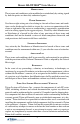
MANAGEMENT FUNCTIONS XP SOFTWARE ARCHITECTURE WITHOUT PRISM (VENDOR DEPENDENT MODE) DESCRIPTION: There will be situations where a client has a need for Triton hardware, service providers and KAL middleware but not Prism application. In this example, Triton provides the ATM, KAL middleware, service providers, and VDM (VENDOR DEPENDENT MODE application). The VDM is somewhat equivalent of the Prism Management functions but with very limited functionality.
M ODEL RL/FT5000 XP U SER M ANUAL VENDOR DEPENDENT MODE (VDM) MAIN MENU Pages 57-63 Pages 64-67 Pages 68-70 Pages 71-74 Pages 75-77 Pages 153-155 Pages 140-144 Pages 85-96 152
MANAGEMENT FUNCTIONS JOURNAL PRINTER ACCESS INSTRUCTIONS: 1. From the MAIN MENU screen (VDM), select the JOURNAL PRINTER option by pressing number <6> on the keypad. DESCRIPTION: The JOURNAL PRINTER option allows the terminal operator to perform the following functions: 1. DEVICE STATUS. Displays a management report that shows properties of the journal printer, such as printer name, assigned port, driver version, and printer resolution. 2. PRINT TEST DATA.
M ODEL RL/FT5000 XP U SER M ANUAL DEVICE STATUS ACCESS INSTRUCTIONS: 1. From the JOURNAL PRINTER screen, select the DEVICE STATUS option by pressing number <1> on the keypad. DESCRIPTION: The DEVICE STATUS function displays a report that shows the current operational status of the journal printer type, firmware version, SP version, device status (Healthy, Fatal, or No Device), media status (Present / Not Present), paper status (Full, Low, or Out), and printer position.
MANAGEMENT FUNCTIONS PRINT TEST DATA ACCESS INSTRUCTIONS: 1. From the JOURNAL PRINTER screen, select the PRINT TEST DATA option by pressing number <2> on the keypad. DESCRIPTION: The PRINT TEST DATA function re-initializes and then performs an operational test of the journal printer. A pattern of characters is printed out to the journal printer using the variety of characters, fonts, and sizes to test the print capability.
M ODEL RL/FT5000 XP U SER M ANUAL XP SOFTWARE ARCHITECTURE WITHOUT PRISM (3RD PARTY APPLICATION) DESCRIPTION: There will also be situations where a client will not be interested in Prism application, service providers and KAL middleware. In this example, Triton will only provide the ATM and Windows XP operating system. The client will install their own 3rd party application to replace Prism and use 3rd party XFS and SP’s to access the ATM hardware devices.
SECTION 6 ERROR CODES (WOSA/TERMINAL) 157
M ODEL RL/FT5000 XP U SER MANUAL INTRODUCTION Prism uses Microsoft WOSA (Windows Open System Architecture) eXtensions for Financial Services (XFS) to “talk” to peripheral hardware devices (card reader, printer, dispensers, etc). When a problem occurs with these devices, an error code (WOSA) is sent to the financial institution. The terminal will also display Triton-specific error codes that most of you are familiar with. The following tables list both the WOSA and associated Triton error codes.
ERROR CODES (WOSA / TERMINAL) NM D Error Code s WOSA C ode 14 Description Triton Decimal C ode Description 303 Lifts are dow n 306 Feed failure XFS hardw are error 159 307 Transmission error 309 Jam in Note Qualifier (NQ) 310 Feed cassette not present 311 Dispenser offline. Configuration record siz e invalid 313 Dispenser offline. Cassette hopper map invalid. 314 Dispenser offline. Can not resolve dispense count.
M ODEL RL/FT5000 XP U SER MANUAL NM D Error Code s WOSA C ode Description Triton Decimal C ode Description 15 Internal error 308 Illegal command / sequence 300 Invalid currency 304 Rejected notes 308 Illegal command / sequence 325 Note Qualifier Unit (NQU) faulty Illegal command / sequence 301 Invalid teller ID 308 302 Cash unit error 302 Empty casette 351 Module needs service 308 Illegal command / sequence 321 Cassette data corrupt 332 Cassette may have b een ch an g ed 303
ERROR CODES (WOSA / TERMINAL) NM D Error Code s WOSA C ode Description Triton Decimal C ode Description 314 Shutter closed 327 Shutter failure 351 Module needs service 315 Invalid cash unit 308 Illegal command / sequence 316 No bills 302 Empty cassette 316 Delivery failure 351 Module needs service 317 Exchange active 308 Illegal command / sequence 318 No exchange activity 308 Illegal command / sequence 319 Shutter not closed 327 Shutter failure 320 Prerror no bills 302 E
M ODEL RL/FT5000 XP U SER MANUAL Card Re ade r Error Code s WOSA C ode Description Triton Decimal C ode Description 542 Device busy 544 Invalid request 550 Card not removed 550 Card not removed 13 14 XFS hardw are error 15 Internal error 48 200 Media jam 201 No media 546 No data 202 Media retained 578 Card present timeout 203 Retain bin full 196 Card reader error 204 Invalid data 539 Invalid track 205 Invalid media 536 Device read error 206 Form not found 544 Invalid
ERROR CODES (WOSA / TERMINAL) Re ce ipt Printe r Error Code s WOSA C ode Description Triton Decimal C ode Description 138 Print failure to receipt 04 14 XFS hardw are error 138 Print failure to receipt 100 Form not found 138 Print failure to receipt 101 Field not found 138 Print failure to receipt 102 No media present 183 Receipt paper low 103 Read not supported 195 Printer out of paper 104 Flush fail 138 Print failure to receipt 105 Media overflow 138 Print failure to recei
M ODEL RL/FT5000 XP U SER MANUAL THIS PAGE INTENTIONALLY LEFT BLANK 164
APPENDIX A ELECTRONIC LOCK A-1
M ODEL RL/FT5000 XP U SER M ANUAL ENTERING THE COMBINATION The electronic lock combination consists of six digits. Upon arrival, the combination of the lock should already be set at 1-2-3-4-5-6. After installation of the unit has been completed, perform the following steps: 1. Enter the preset combination and check for proper operation. After each keypress, the lock will beep. After the final digit has been entered, the lock will beep twice and the open period will begin. 2.
APPENDIX A - ELECTRONIC LOCK BATTERY LOW WARNING Repeated beeping during an opening indicates that the battery is low or dead and needs to be replaced. The battery box is located on the inside of the door. Note: If the lock will not operate (i.e. repeated beeping or no beeping) while the door is closed and locked, the battery must be energized from the two external terminals on the front of the push-button panel. To energize the lock, connect a 9-volt alkaline battery on the external terminal points.
M ODEL RL/FT5000 XP U SER M ANUAL This Page Intentionally Left Blank A-4
APPENDIX B GLOSSARY OF TERMS B-1
M ODEL RL/FT5000 XP U SER M ANUAL Glossary of Terms ANSI - American National Standards Institute The US government body responsible for approving US standards in many areas, including computers and communications. ANSI is a member of ISO (International Standards Organization). ANSI sells ANSI and ISO standards ASCII - American Standard Code for Information Interchange A code for information exchange between computers made by different companies; a string of 7 binary digits represent each character.
APPENDIX B - GLOSSARY OF TERMS Glossary of Terms ISO - Independent Sales Organization LUNO - Logical Unit Number A 3-bit identifier used on a SCSI bus to distinguish between up to 8-devices (logical units) with the same SCSI ID. LUO – Logical Unit A primary component of SNA, an LU is a type of NAU that enables end users to communicate with each other and gain access to SNA network resources.
M ODEL RL/FT5000 XP U SER M ANUAL Glossary of Terms SNA – Systems Network Architecture IBM’s proprietary high level networking protocol standard. Subnet Mask A bit mask used to identify which bits in an IP address correspond to the network address and subnet portions of the address. This mask is referred to as the subnet mask because the network portion of the address can be determined by the class inherent in an IP address.
Triton Systems of Delaware, INC. Software Release Notes Prism 1.0.21 Affected products RL5000/FT5000XP June 24, 2008 Version 1.3 Triton Systems of Delaware, Inc.
INTRODUCTION......................................................................................................................... 3 PLATFORMS AFFECTED......................................................................................................... 3 HARDWARE REQUIREMENTS ........................................................................................................ 3 NEW FEATURES ADDED ......................................................................................................
Introduction This document describes the changes to the RL5000/FT5000XP 1.0.21 software version for Prism5K. Platforms Affected This release is for the following PrismXP families: • RL5000 • FT5000 Hardware Requirements • • RL5000 FT5000 New Features Added Graphic Printing This release added the ability to print graphics and coupons on receipts. The Prism and WebComponents 1.0.0.4 applications were changed to support this functionality.
The Partial Dispense Status byte will be ‘5’ for cassette low and cassette out messages sent to the host. However, when the last cassette goes to a cassette out situation, the status byte will be ‘3’. Function Commands not processed This release addresses the situation where Function Commands sent by the host where not received by the terminal. Installing TLF updates Management Functions has an option in System Parameters called Perform Software Updates.
Saving TcpIP settings in Prism When you select the option to “Save” on the Host Communication Protocol Settings menu, the settings are saved by Prism. There was a situation addressed in this release, where it was required to save the settings twice before they took affect. Port Number Reset On the Host Communication Protocol Settings menu, there is an option for Port Number. This release corrected the situation where the Port Number was incorrectly reset to the default (2000) after a system reboot.
Known Issues When installing the 1.0.21 update load file (tlf) on top of version 1.0.20, the “Port Number” setting in “Terminal Configuration > Communication > Host Communication Protocol Settings” may be reset back to the default value of 2000 if the server mode is set to “Server”. Revision History Date April 25, 2008 May 9, 2008 Version 1.0 1.1 May 28, 2008 1.2 June 24, 2008 1.3 Triton Systems Description of Change Initial Release Modified release notes to remove bug report list.
Triton Systems of Delaware, INC. Software Release Notes 1.0.22 Affected products RL5000/FT5000 XP December 10, 2008 Version 1.0 Triton Systems of Delaware, Inc.
INTRODUCTION......................................................................................................................... 3 PLATFORMS AFFECTED......................................................................................................... 3 HARDWARE REQUIREMENTS ........................................................................................................ 3 SOFTWARE REQUIREMENTS ...................................................................................................
Introduction This document describes the changes to the RL5000/FT5000 XP 1.0.22 software version for Prism. Platforms Affected This release is for the following PrismXP families: • RL5000 • FT5000 Hardware Requirements • • RL5000 FT5000 Software Requirements The following load files are included with this release: • Prism5K-1_0_22_0.tlf – Update load for Field Upgrades • Prism5K-1_0_22_0_Lockdown.tlf – Update load for Field Upgrades Important: The TLF installer requires with Prism5K 1.00.00.
The Partial Dispense Status byte will be ‘5’ for cassette out messages sent to the host. However, when the last cassette goes to a cassette out situation, the status byte will be ‘3’. Function Command (FC) sent by host not received at terminal There was a situation where the terminal didn’t receive the transaction replies from the host because the host sent two (2) function commands inside one (1) TcpIp packet. The terminal will now separate each host message from the TcpIp packet.
Triton Systems of Delaware, INC. Software Release Notes 1.0.23 Affected products RL5000/FT5000 XP April 10, 2009 Version 1.0 Triton Systems of Delaware, Inc.
INTRODUCTION......................................................................................................................... 3 PLATFORMS AFFECTED......................................................................................................... 3 HARDWARE REQUIREMENTS ........................................................................................................ 3 SOFTWARE REQUIREMENTS ...................................................................................................
Introduction This document describes the changes to the RL5000/FT5000 XP 1.0.23 software version for Prism. Platforms Affected This release is for the following PrismXP families: • RL5000 • FT5000 Hardware Requirements • • RL5000 FT5000 Software Requirements The following load files are included with this release: • Prism5K-1_0_23_0.tlf – Update load for Field Upgrades • Prism5K-1_0_23_0_Lockdown.tlf – Update load for Field Upgrades Important: The TLF installer requires with Prism5K 1.00.00.
TcpIp: terminal in Server mode not reconnecting after disconnect In some situations where the terminal was configured as a Server, it did not reconnect to the host (client) after a disconnection occurred. In this release, the Server terminal will attempt to reconnect whenever the host disconnects. Read Card State: should return to default State0 when previous transaction’s closing state doesn’t exist There was a situation where the Next State in the Function Command, received from the host, didn’t exist.
Known Issues • None Revision History Date 4/10/09 Triton Systems Version 1.