MODEL RL2000 AUTOMATED TELLER MACHINE INSTALLATION MANUAL TDN 07103-00155 Jan 8, 2013 CORPORATE HEADQUARTERS 21405 B St. Long Beach, MS 39560 Phone: (800) 259-6672 Fax: (228) 868-9445 COPYRIGHT NOTICE © 2013 Triton. All Rights Reserved. TRITON logo is a registered trademark of Triton Systems of Delaware, LLC.
MODEL RL2000 INSTALLATION MANUAL INTRODUCTION The Triton RL2000 is a lobby terminal designed for indoor use only. The following sections provide the requirements for installing the RL2000 for your particular site location. To assist you in preparing your site, a check list is provided of various steps that should be carried out prior to the arrival of the ATM. WHAT’S IN THIS INSTALLATION GUIDE This Installation Guide provides information for the physical installation of the RL2000 ATM.
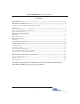
MODEL RL2000 INSTALLATION MANUAL CONTENTS SITE COMPLIANCE ......................................................................................................... 4 ENVIRONMENTAL PRECAUTIONS ...................................................................................... 5 TEMPERATURE / POWER / RF INTERFERENCE REQUIREMENTS ........................................................................ 6 DIMENSIONS ............................................................................................
MODEL RL2000 INSTALLATION MANUAL SITE COMPLIANCE This document contains the information necessary for the preparation and installation of an RL2000 Triton ATM. It’s important that the site complies with the requirements specified in this document. In addition, electrical wiring and mechanical systems must also comply with all relevant laws and regulations. The site must be prepared by the customer or his agent who is fully conversant with the requirements of installing ATM equipment.
MODEL RL2000 INSTALLATION MANUAL ENVIRONMENTAL PRECAUTION CHECKLIST 5
MODEL RL2000 INSTALLATION MANUAL When installing an ATM, some general environmental and power precautions need to be considered. Evaluate the location where the ATM will be installed. To help ensure proper operation of the ATM, ensure the environmental criteria listed in this checklist are met. TEMPERATURE / HUMIDITY 1. * IMPORTANT * AC power for the terminal should come from a dedicated source with an isolated ground. The ATM will operate over a range of temperatures and humidity.
MODEL RL2000 INSTALLATION MANUAL DIMENSIONS Dimensions listed comply with US Federal ADA Guidelines. For USA installations, check for additional guidance. For non-USA installations, check regulations relating to the country of install.
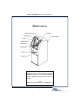
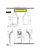
MODEL RL2000 INSTALLATION MANUAL PHYSICAL DIMENSIONS Front View Customer Access Dimensions Feature Height 1 Top Function Key 45" [1144 mm] 2 #5 K ey (Main Keypad) 36" [914 mm] 3 Card Reader 38 - 15/16" [988 mm] 4 Receipt Printer 38 - 5/8" [982 mm) 5 Bill Tray 25 - 3/16" [640 mm] 8
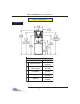
MODEL RL2000 INSTALLATION MANUAL S ERVICE A REA D IMENSIONS 2" [51] clearance around cabinet sides and rear Dimensions Show n in inches (") and [millimeters] Dimension Level 1 (Vault) Business Hours A ~ 21" [533] ~ 21" [533] B 28-1/16" [560] 27-3/8" [696] C 22-1/16" [560] 21-3/8" [543] D 14-1/2" [368] 9" [229] E 30" [762] 28" [711] 9
MODEL RL2000 INSTALLATION MANUAL PHYSICAL DIMENSIONS (DEEP CABINET - BUSINESS HOURS) Side Views 10
MODEL RL2000 INSTALLATION MANUAL PHYSICAL DIMENSIONS (DEEP CABINET - BUSINESS HOURS) Mid Topper High Topper 11
MODEL RL2000 INSTALLATION MANUAL PHYSICAL DIMENSIONS (DEEP CABINET - VAULT) Side View CABINET “FOOTPRINTS” Anchor “footprint” - Deep cabinet (Business) Anchor “footprint” - Deep cabinet (Vault) F r o n t F r o n t 12
MODEL RL2000 INSTALLATION MANUAL DECAL AREA DEEP CABINET 13
MODEL RL2000 INSTALLATION MANUAL 14
MODEL RL2000 INSTALLATION MANUAL DECAL AREA VAULT CABINET 15
MODEL RL2000 INSTALLATION MANUAL 16
MODEL RL2000 INSTALLATION MANUAL CABINET INSTALLATION 17
MODEL RL2000 INSTALLATION MANUAL CABINET INSTALLATION The following procedure applies to installing the cabinet assembly using either standard (P/N 06200-00066) or chemical (06200-00060) anchor kits. The anchor kits are not supplied with the unit.
MODEL RL2000 INSTALLATION MANUAL 5. Stand the unit up and walk it out of the shipping carton. 6. Remove the wrapping from the ATM. 7. Use the silver key to unlock both the control panel and the fascia door (which conceals the locking mechanism) on the front of the cabinet. Open the fascia door. 8. Lift the handle under the bill chute to open the front enclosure door. If the door is locked, see the sidebar on this page for help in unlocking the electronic or mechanical lock, if applicable.. 9.
MODEL RL2000 INSTALLATION MANUAL Mark/Drill Mounting Holes SELECTING THE INSTALLATION LOCATION Mark the location of the cabinet mounting holes on the concrete floor. This is accomplished as described below: Choosing the right location for your ATM is very important. Security concerns suggest a location that is away from any door or external access point. Ideally, the terminal should be mounted as close to a back wall as possible.
MODEL RL2000 INSTALLATION MANUAL 4. Use a portable vacuum cleaner to remove any dust or debris that may have fallen into the holes during the drilling process. Drill anchor holes Blow out dust/debris. Install Standard Anchors Bolt ATM to Floor 1. Ensure the leveling feet are flush with the bottom of the cabinet. If necessary, use a screwdriver to adjust the leveling bolts inside the cabinet (near the four corners) so that the leveling feet are flush with the bottom of the cabinet.
MODEL RL2000 INSTALLATION MANUAL 4. Place a flat washer on the anchor bolt followed by a 1/2” (13mm) nut. 5. Repeat Steps 2 and 3 for the remaining anchor bolts. 6. Ensure the cabinet is as level as possible given the floor conditions. Use a bubble level to verify this. If a bubble-level is not available, the cabinet can be “rocked” gently from front-to-back and side-toside to check the need for leveling. 7.
MODEL RL2000 INSTALLATION MANUAL 6. Insert the chisel point of the rod into the hole to break the glass capsule. Spin it into the capsule at a speed of 250 to 500 RPM, until it is fully embedded. IMPORTANT! Turn the rotary hammer drill OFF IMMEDIATELY when the rod is fully embedded! 7. Pull the driver out of the coupling while holding the rod. Hold the hex nut with a wrench to unthread the coupler. 8. Repeat steps 1-7 for each of the remaining mounting holes. 9.
MODEL RL2000 INSTALLATION MANUAL THIS PAGE INTENTIONALLY LEFT BLANK 24
MODEL RL2000 INSTALLATION MANUAL 3. Secure/plug the unused access hole with the grommet or plug provided.
MODEL RL2000 INSTALLATION MANUAL Route AC Power and Communication Cable NOTE: Before you start, unlock and open the control panel. Verify that the power switch on the unit’s power supply is in the OFF (0) position. Close the control panel. NOTE The Power Cord interface cable is located inside the vault area (Dispenser location) of the cabinet. To gain access and connect the power cord included in the accessory box, you may have to remove the dispenser. 1.
MODEL RL2000 INSTALLATION MANUAL Power Outlet Accessibility Whether you are installing a new AC socket outlet or plan to use an existing outlet to supply power to the ATM, make sure the following requirements are met: 1. The outlet is located near the equipment. 2. AC power for the terminal should come from a dedicated source with an isolated ground. The ATM is designed to work on an IT (Isolated-Terra) type power system having a phase-to-phase voltage not exceeding 240 volts. 3.
MODEL RL2000 INSTALLATION MANUAL TCP/IP (ETHERNET) The Ethernet option makes your RL2000 ATM LAN (Local Area Network) or WAN (Wide Area Network) capable. The ATM functions that are normally performed via the dial-up telephone system, such as customer transactions and remote monitoring, can now be performed using existing in-house communications network. ATM transaction processing and hardware monitoring functions are performed across a shared network medium.
MODEL RL2000 INSTALLATION MANUAL VSAT (SATELLITE) VSAT stands for “Very Small Aperture Terminal” and refers to receive/transmit terminals installed at dispersed sites connecting to a central hub via satellite using small diameter antenna dishes (0.6 to 3.8 meter). VSAT technology represents a cost effective solution for users seeking an independent communications network connecting a large number of geographically dispersed sites.
MODEL RL2000 INSTALLATION MANUAL THIS PAGE INTENTIONALLY LEFT BLANK 30
APPENDIX A SOFTWARE LICENSE AGREEMENT COMPLIANCE / EMISSION STATEMENTS
APPENDIX A - SOFTWARE LICENSE AGREEMENT / COMPLIANCE/EMISSION STATEMENTS AUTOMATED TELLER MACHINE (“ATM”) SOFTWARE END-USER AGREEMENT IMPORTANT: PLEASE READ CAREFULLY: BY INSTALLING OR OTHERWISE USING THE ATM, YOU (AS THE OWNER OR LESSEE OF THE ATM).
APPENDIX A - SOFTWARE LICENSE AGREEMENT / COMPLIANCE/EMISSION STATEMENTS DISCLAIMER OF WARRANTIES AND LIMITATION OF DAMAGES TO THE EXTENT PERMITTED BY LAW, THIS ATM SOFTWARE, INCLUDING ALL INCORPORATED THIRD PARTY SOFTWARE, AND DERIVATIVES IS PROVIDED, “AS IS”. TRITON MAKES NO REPRESENTATIONS WITH RESPECT TO, AND DOES NOT WARRANT THE PERFORMANCE OR RESULTS YOU OR YOUR CUSTOMERS MAY OBTAIN BY USING THE ATM.
APPENDIX A - SOFTWARE LICENSE AGREEMENT / COMPLIANCE/EMISSION STATEMENTS COMPLIANCE / EMISSION STATEMENTS DISCLAIMER The manufacturer of the Automated Teller Machine (ATM) product(s) described herein makes no representations or warranties, either expressed or implied, by or with respect to anything in this manual, and shall not be liable for any implied warranties of fitness for a particular purpose or for any indirect, special, or consequential damages.
APPENDIX B ATM INSTALLATION FOR ACCESSIBILITY
APPENDIX B - ATM INSTALLATION FOR ACCESSIBILITY A Guide to the New ADA-ABA Accessibility Guidelines On July 23, 2004, the U.S. Access Board, an independent Federal agency, issued updated accessibility guidelines for new or altered facilities covered by Americans with Disabilities Act and the Architectural Barriers Act. These guidelines address a wide range of facilities in the private and public sectors. Presented here is an overview of the new guidelines that also highlights significant changes.
APPENDIX B - ATM INSTALLATION FOR ACCESSIBILITY 305.4 Knee and Toe Clearance. Unless otherwise specified, clear floor or ground space shall be permitted to include knee and toe clearance complying with 306. 305.5 Position. Unless otherwise specified, clear floor or ground space shall be positioned for either forward or parallel approach to an element. Figure 305.5 Position of Clear Floor or Ground Space 305.6 Approach.
APPENDIX B - ATM INSTALLATION FOR ACCESSIBILITY 308. Reach Ranges 308.1 General. Reach ranges shall comply with 308. 308.2 Forward Reach. 308.2.1 Unobstructed. Where a forward reach is unobstructed, the high forward reach shall be 48 inches (1220 mm) maximum and the low forward reach shall be 15 inches (380 mm) minimum above the finish floor or ground. Figure 308.2.1 Unobstructed Forward Reach 308.2.2 Obstructed High Reach.
APPENDIX B - ATM INSTALLATION FOR ACCESSIBILITY 308.3 Side Reach. 308.3.1 Unobstructed. Where a clear floor or ground space allows a parallel approach to an element and the side reach is unobstructed, the high sidereach shall be 48 inches (1220 mm) maximum and the low side reach shall be 15 inches (380 mm) minimum above the finish floor or ground. EXCEPTIONS: 1.
APPENDIX B - ATM INSTALLATION FOR ACCESSIBILITY ATM INSTALLATION FOR ACCESSIBILITY 1. This document supersedes all other information provided by Triton for ATM installation for accessibility. 2. Information provided in this manual is based on federal guidelines (ADA Accessibility Guidelines for Buildings and Facilities – ADAAG) as amended through January 1998. You should verify it has not been amended. States may also have accessibility codes.
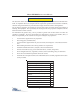
APPENDIX B - ATM INSTALLATION FOR ACCESSIBILITY ACCESSIBILITY SPECIFICATIONS REACH DEPTH Inche s M illime te rs 10 11 12 13 M AXIM UM HEIGHT Inche s M illime te rs 255 54 137 0 28 0 53 1/2 1360 305 53 1345 330 52 1/2 1335 14 355 51 1/2 1310 15 380 51 1295 16 405 50 1/2 1285 17 430 50 1270 18 455 49 1/2 1255 19 4 85 49 1245 20 510 48 1/2 1230 21 535 47 1/2 1205 22 560 47 1195 23 585 46 1/2 1180 24 610 46 1170 (3) Forward and Parallel Approach.
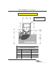
APPENDIX B - ATM INSTALLATION FOR ACCESSIBILITY 4.2.4 Clear Floor or Ground Space for Wheelchairs. 4.2.4.1 Size and Approach. The minimum clear floor or ground space required to accommodate a single, stationary wheelchair and occupant is 30 inches by 48 inches (760 mm by 1220 mm) (see Fig.4a). The minimum clear floor or ground space for wheelchairs may be positioned for forward or parallel approach to an object (see Fig. 4b and 4c).
APPENDIX B - ATM INSTALLATION FOR ACCESSIBILITY Figures 4d. Clear Floor Space in Alcoves. Figures 4e. Clear Floor Space in Alcove. For a side approach, where the depth of the alcove is equal to or less than 15 inches (380 mm), the required clear floor space is 30 inches by 48 inches (760 mm by 1220 mm).
APPENDIX B - ATM INSTALLATION FOR ACCESSIBILITY Figure 5b. Forward reach, obstructed. 4.2.6 Side Reach. If the clear floor space allows parallel approach by a person in a wheelchair, the maximum high side reach allowed shall be 54 inches (1370 mm) and the low side reach shall be no less than 9 inches (230 mm) above the floor (Fig. 6(a) and 6(b)). If the side reach is over an obstruction, the reach and clearances shall be as shown in Fig 6(c). Figure 6a. Parallel approach - side reach. Figure 6b.
APPENDIX B - ATM INSTALLATION FOR ACCESSIBILITY THIS PAGE INTENTIONALLY LEFT BLANK B-12