
Installation Guide


P3
OFF
OFF
OFF
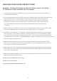
Turn off power at breaker
box to avoid possible
electrical shock.
Use metal outlet box suitable
for fan support.
Outlet box must support 35 lbs min.
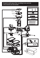
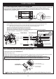
Installing mounting plate to ceiling outlet box
CAUTION:
Oscillating device located
at hanging base is fragile,
do not damage or bend
oscillating parts (cam/arm/motor)
during installation
Note 1: Note 2: Note 3:
cam
motor
arm
Hanging Base
Mounting Plate
Outlet Box
House Wires
1A.
Pull house wires from outlet
box through the center hole
of mounting plate
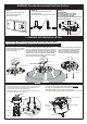
Direction Mark
Outlet Box
Screw hole
Mounting slot
Outlet Box
Mounting
Plate
( fig.1)
1B.
Direction marks are for finding the air
direction. Direction marks show the certerline
position between the motors. Motors will be
90 degrees to the left and right of the direction
mark. Adjust mounting plate to the desired
position by aligning 2 slots of mounting plate
with screw holes on outlet box.
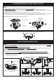
1E. Hanging the fan
Lift the fan assembly and hang onto the
through oval-shaped hole on mounting plate.
This will permit you to make the electrical
connections without having to hold the fan up as well.
J hook
Mounting Plate
J Hook
Downrod
Canopy
Hanging Base
Remote
Receiver
1D. Yoke & Downrod Assembly
Yoke
Cross Pin
Canopy
Cotter Pin
Fan Assembly
Cotter Pin
Set Screw
Cross Pin
( fig.2)
( fig.3)
Remove cotter pin and cross pin secured on downrod
and pull out lead wires inside downrod slightly and
insert downrod into yoke (see fig. 2).
Attached cotter pin and cross pin back through yoke
and downrod securely (see fig. 3).
M
a
x
i
m
u
m
s
w
e
e
p
a
r
e
a
:
5
8
3
s
q
u
a
r
e
f
e
e
t
(
5
4
.
2
s
q
u
a
r
e
m
e
t
e
r
)
WARNING: Fan should be at least 7 feet from the floor
1. HANGING SYSTEM INSTALLATION
1C.
Attach mounting plate to outlet box
by securing with screws included
with the outlet box and washers
from the hardware bag through 2
out of 6 slots on mounting plate.
IMPORTANT: Align Mounting Plate to desired oscillator direction now.