
Installation Guide


P5
Screws on
Mounting Plate
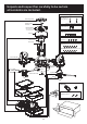
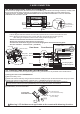
3. HANGING BASE AND CANOPY INSTALLATION
3B. Push up canopy and secure to hanging base with 4 set screws from hardware bag.
Mounting Plate
Hanging Base
Hanging Base
1
4
( fig.1) ( fig.2)
3
3A.
Carefully lift the fan assembly away from the hook on mounting plate.
Slightly rotate hanging base until two screw heads are in L type slots.
Attach other 2 set screws from hardware bag to secure hanging base and mounting plate (these will be
the remaining 2 out of 4 set screws for securing hanging base to mounting plate).
1
2
Align direction marks direction markson mounting plate with on hanging base.
Push up hanging base until 2 set screws pre-installed on mounting plate are engaged with L type slots
on hanging base.
Make sure all 4 set screws are firmly secured.
(see fig.1)
(see fig.1)
(see fig.2)
(see fig.2)
3
4
Note:
Canopy
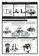
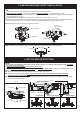
4. SET UP MOTOR POSITION
Motor Yoke
For 0 degree
Downrod Yoke
Motor Yoke
Downrod Yoke
For 45 degree For 90 degree
Motor Yoke
Downrod Yoke
Downrod Yoke
Set Screw
Motor Yoke
( fig.1)
( fig.2)
Set Screw
Set Screw
Set Screw
NOTE:
1.Fan motor is at 0 degree when taken out from the carton, no need to change motor angle
2.
if intend
to use the fan at 0 degree.
Both motor positions must be set at the same angle.
There is and for aligning 0/45/90 degree motor
position (see fig. 1)
Remove set screw and spring washer from motor yoke. (see fig. 2)
Adjust motor angle by aligning
.(see fig. 2)
Secure set screw and spring washer removed from step 4A back to motor yoke. Make sure set screw is
firmly tightened.(see fig. 2)
one indicating line on downrod yoke three on motor yoke
one out of three indicating lines (0/45/90) on motor yoke with
indicating line on downrod yoke
4A.
4B.
4C.
Indicating Line(1)
Indicating Line(3)
2
2