
Installation Guide
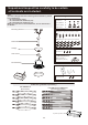

Outlet Box
#1 Fan has completed its set up.
You are ready to set up the #2 Fan.
Outlet Box
#1 Fan
(Disconnecting)
#2 Fan
Mounting Bracket
ON ECE
1
2
3
4
#1 Fan
ON ECE
1
2
3
4
#2 Fan
Troubleshoot
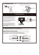
Special note: To install multiple fans with different frequency codes.
If you are installing more than one fan in the same area, the remote setup can affect all fans in the area. To
have precise control over each fan and light, each fan / remote must be set-up by itself. To avoid frequency
interference, please do the following steps so the fans can be operated independently by its own remote.
The following steps are based on the status of
a. First DC fan (#1 fan) has completed its setting and is operating in good condition.
b. Second DC fan (#2 fan) now is completing its assembling steps and ready for “set up”.
c. The main switch is “OFF”.
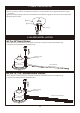
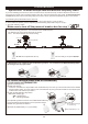
Make sure to turn off the power at breaker box for step 1.
O
F
F
O
F
F
O
F
F
OFF
st
1.Lower the canopy from the 1 Fan and disconnect the Black wire.
Put the wire nut on the black wire from the house.
st
The 1 Fan will remember its current setting.
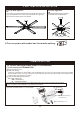
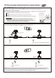
nd
2. Remember to set a different Fan Code Setting on the 2 fan, and follow the Remote Setting steps
7A through 7C from page 6 and 7.
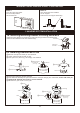
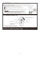
P8
1 Remove battery cover.
2 FAN code setting:
There are 4 switches for 16 possible code combinations just in case your house has other fans installed
with the same codes. You may change your code switches by using a small screwdriver or ball point pen
to slide each code switch up or down.
3 Light "On/Off-Dimming" dip switch:
See below drawing 3
* ON = ON/OFF only
* D = Dimming/ON/OFF
The optional Light Kit for this fan uses a Dimmable LED Array
so this dip switch should remain in the “D” position unless
ON/OFF only operation is desired.
4 Install 12V 23AE battery x 1 pc (included).
7A. Initial Settings (Back side of Transmitter)
1.Code setting on TRANSMITTER.
3
1
ON D
4 12V 23AE Battery x 1 pc
Shows default setting of
“D” for Dimming.
2
ON ECE
1
2
3
4