PAC 2100 X / PAC 2600 X EN TRT-BA-PAC2100X/PAC2600X-TC2019-02-003-EN OPERATING MANUAL LOCAL AIR CONDITIONER
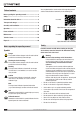
You can download the current version of the operating manual and the EU declaration of conformity via the following link: Table of contents Notes regarding the operating manual................................. 2 Safety ..................................................................................... 2 Information about the device................................................ 5 PAC 2100 X Transport and storage........................................................... 6 Assembly and installation....
• • • • • • • • • • • • • • • This appliance is not a toy! Keep away from children and animals. Do not leave the device unattended during operation. Check accessories and connection parts for possible damage prior to every use of the device. Do not use any defective devices or device parts. Ensure that all electric cables outside of the device are protected from damage (e.g. caused by animals).
PAC 2600 X Intended use Only use the device for cooling, ventilating and dehumidifying indoor air whilst adhering to the technical data. Improper use • • • • Do not place the device on wet or flooded ground. Do not place any objects, e.g. clothing, on the device. Do not use the device outdoors. Any unauthorised modifications, such as alterations or structural changes to the device, are forbidden. Any operation other than as described in this manual is prohibited.
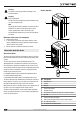
Warning The device is not a toy and does not belong in the hands of children. Device depiction Warning Risk of suffocation! Do not leave the packaging lying around. Children may use it as a dangerous toy. 1 2 11 Note Do not operate the device without an inserted air filter! Without an air filter the inside of the device will be heavily contaminated, which could reduce the dehumidification performance and result in damage to the device. Behaviour in the event of an emergency 3 1.
Transport and storage Assembly and installation Note If you store or transport the device improperly, the device may be damaged. Note the information regarding transport and storage of the device. Transport Scope of delivery • • • • • To make the device easier to transport, it is fitted with wheels. Before transporting the device, observe the following: • Switch off the device. • Hold onto the mains plug while pulling the power cable out of the mains socket.
• • • • • • • • Before restarting the device, check the condition of the power cable. If there are doubts as to the sound condition, contact the customer service. Only position the device in rooms where potentially leaking refrigerant cannot accumulate. Only position the device in rooms where there is no permanent source of ignition (e.g. open flames, an active gas appliance or an electric heater). Set the device up in an upright and stable position.
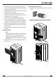
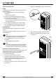
Discharging exhaust air • The exhaust air coming from the device contains waste heat from the room to be cooled. For this reason it is recommended to discharge the exhaust air to the outside. • The end of the exhaust air hose can be fed through the open window. If required, secure the open window with the corresponding means, so that the end of the exhaust air hose cannot shift. • The end of the exhaust air hose can also be hooked into a tilted window.
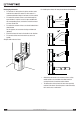
Opening the ventilation flaps 1. Prior to switching the device on, open the ventilation flaps at the air outlet. Operation • Avoid open doors and windows. Operating elements 12 13 Connecting the power cable • Insert the mains plug into a properly secured mains socket. 14 15 16 17 No.
3. Remove the rubber stopper from the hose connection. Setting the operating mode Cooling In cooling mode the room will be cooled down to the desired target temperature. 1. Press the MODE button (12) until the Cool LED (14) is illuminated. ð Cooling mode is selected. 2. Select the desired target temperature by use of the Plus (16) or Minus (13) buttons. Temperatures between 17 °C and 30 °C can be selected. ð The currently selected target temperature is shown on the segment display (15). 3.
6. Guide the other hose end to a suitable drain or sufficiently dimensioned collection container. To ensure that the condensate can run off, the condensation drain hose must not be kinked, nor should it have to overcome an uphill incline towards the drain. Changing the unit °C / °F The temperature can be indicated in either °C or °F on the remote control's display (19) and on the segment display (15) of the device. 1. Simultaneously press and hold the Plus (16) and Minus (13) buttons for 3 s.
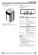
Remote control All settings of the device can also be made using the remote control included in the scope of delivery. Insert suitable batteries in the remote control (see chapter Technical annex). Info After a longer period of non-use, the remote control will switch to standby mode. Standby mode can be terminated by pressing the ON/OFF button (33) on the remote control. The device automatically uses the current settings entered via the remote control. No.
Setting the timer The timer has two modes of operation: • automatic switch-on upon expiry of a preset number of hours • automatic switch-off upon expiry of a preset number of hours The timer can be programmed in increments of 0.5 hours (0 to 10 h) or in increments of 1 hour (10 to 24 h). This setting can only be made using the remote control. The function can be set in all operating modes. It can be activated both during operation and in standby mode.
Switching the LEDs on the control panel on or off The control panel illumination at the devices can be switched on and off. This setting can only be made using the remote control. 1. Press the LED button (23). ð The LEDs on the control panel will be switched off. ð The device continues to run with the selected settings. 2. Press the LED button (23) again. ð The LEDs on the control panel will be switched back on.
The device works with reduced or no cooling capacity: • Check whether cooling mode is selected. • Check the proper fit of the exhaust air hose. In case of kinks, bends or blockage in the hose, exhaust air cannot be discharged. Clear the way for the exhaust air. • Check the position of the ventilation flaps. They should be opened to the maximum. • Check the air filter(s) for dirt. If necessary, clean or replace the air filter(s). • Check the minimum distance to walls or other objects.
Maintenance intervals Maintenance Maintenance and care interval before every start-up as needed at least every 2 weeks at least every 4 weeks X Check the air inlets and outlets for dirt and foreign objects and clean if necessary at least every 6 months at least annually X Clean the exterior X X Visually check the inside of the device for dirt X X X Check the air filter for dirt and foreign objects and clean or replace if necessary X X Replace the air filter X Check for damage X Check
Activities required before starting maintenance • • 5. Put the air filter back in. Warning of electrical voltage Do not touch the mains plug with wet or damp hands. Switch the device off. Hold onto the mains plug while pulling the power cable out of the mains socket. Warning of electrical voltage Tasks which require the housing to be opened must only be carried out by authorised specialist companies or by Trotec.
2. Remove sealing cap and rubber stopper from the condensate outlet. 4. Reinsert the air filter into the device. Condensate discharge (manual draining) In cooling and dehumidification mode condensate is formed, which is mostly discharged via the exhaust air. The remaining condensate is collected in a container within the housing. The condensate ought to be drained regularly.
Activities required after maintenance If you want to continue using the device: • Leave the device to rest for 12 to 24 hours, so the refrigerant can accumulate within the compressor. Wait 12 to 24 hours before switching the device back on! Acting contrary might lead to compressor damage and a malfunctioning device. If so, any warranty claims will be voided. • Reconnect the device to the mains.
Technical data Technical annex Model PAC 2100 X PAC 2600 X Cooling capacity 2.0 kW 2.6 kW Dehumidification performance 1.8 l/h 2.1 l/h Operating temperature 17 °C to 35 °C 17 °C to 35 °C Temperature setting range 17 °C to 30 °C 17 °C to 30 °C 3 Max. air volume flow 310 m /h 295 m3/h Mains connection 1/N/PE~ 220 V – 240 V / 50 Hz 1/N/PE~ 220 V – 240 V / 50 Hz Nominal current 5.0 A 6.22 A Power input (cooling operation) 0.75 kW 1.
Trotec GmbH & Co. KG Grebbener Str. 7 D-52525 Heinsberg +49 2452 962-400 +49 2452 962-200 info@trotec.com www.trotec.