TTK 400 DE Bedienungsanleitung – Bautrockner TTK 400 .................................... A - 1 EN Operating Manual – Construction dryer TTK 400............................... B - 1 FR Manuel d'utilisation – Déshumidificateur de chantier TTK 400 ........ C - 1 IT Istruzioni per l'uso – Essiccatore edile TTK 400................................. D - 1 NL Bedieningshandleiding – Bouwdroger TTK 400 .................................
Gewährleistung Inhaltsverzeichnis Die Gewährleistung beträgt 12 Monate. Schäden infolge von Fehlbedienung durch nicht eingewiesenes Personal oder Inbetriebnahme durch nicht autorisierte Personen sind von der Gewährleistung ausgeschlossen. Das Gerät entspricht den grundlegenden Sicherheits- und Gesundheitsanforderungen der einschlägigen EU-Bestimmungen und wurde werkseitig mehrfach auf einwandfreie Funktion geprüft.
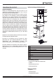
Gerätedarstellung und Bedienelemente Informationen über das Gerät Gerätebeschreibung 1 Mithilfe des Kondensationsprinzips sorgt das Gerät für eine automatische Luftentfeuchtung von Räumen. Hierzu kann das Gerät im Dauerbetrieb verwendet werden. Der Ventilator saugt die feuchte Raumluft am Lufteinlass (2) über den Luftfilter (5), den Verdampfer und dem dahinterliegenden Kondensator an. Am kalten Verdampfer wird die Raumluft bis unter den Taupunkt abgekühlt.
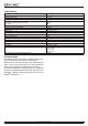
Technische Daten Parameter Wert Modell Entfeuchterleistung, max. Entfeuchterleistung (20 °C / 60 % relative Luftfeuchtigkeit) geeignet für Raumgrößen bis: Bautrocknung oder Wasserschadensbeseitigung Trockenhaltung Betriebstemperatur Arbeitsbereich relative Luftfeuchtigkeit Luftleistung, max. Elektroanschluss Leistungsaufnahme, max.
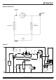
Diagramm Kältekreislauf PROCESS PORT SOLENOID VALVE COMP L HIGH AIR LIMIT STAT HUMIDISTAT REMOVE LINK IF PUMP FITTED HP SWITCH BREAKS ON PRESSURE RISING (N/C)L LP SWITCH BREAKS ON PRESSURE FALLING CONTROL FUSE CONTACTOR 5 6(NO) HOURS RUN METER A2 2(NO) DELAY TIMER 2 1 1 2 H(N/C) C(COM) C(COM) 1 RUN CAP 1 (N/O) DEFROST THERMOSTAT (COM) 3 4 (N/C) RELAY/HARD START CAP (IF FITTED) R COMPRESSOR S C DEFROST LAMP DEFROST VALVE 2 TEMP FALLING MAKES 1-3 ON FAN MOTOR FAN CAP' S
ISS 1 INITIAL ISSUE TB8 1 2 3 4 R C S COMPRESSOR MOTOR FAN SOLENOID VALVE METER kW HOURS RUN CAP IF FITTED HARD START CAP ON/OFF SWITCH ISOLATOR N TB11 3 2 STAT CONTROL DEFROST PUMP PLUG M/C PLUG IF FITTED WITH PUMP PLUG REMOVE & REPLACE TB10 TB9 DRAWING CHANGE 4 1 TB12 HUMIDISTAT IF FITTED L C/N 1394 DATE 19/01/10 HIGH LEVEL FLOAT SWITCH APPD KW ASPEN PUMP 1 LOW LEVEL FLOAT SWITCH PURGE PUSH BUTTON 2 ASPEN PUMP KIT OPTION 2 4 1 FINISH MATERIAL SOCK
Bestimmungsgemäße Verwendung Verwenden Sie das Gerät TTK 400 ausschließlich als mobilen Lesen Sie diese Anleitung vor Inbetriebnahme / Verwendung Industrietrockner zum Trocknen und Entfeuchten der Raumluft, des Gerätes sorgfältig und bewahren Sie sie immer in unter Einhaltung der technischen Daten. unmittelbarer Nähe des Aufstellortes bzw. am Gerät auf! Zur bestimmungsgemäßen Verwendung gehören: • Betreiben Sie das Gerät nicht in explosionsgefährdeten • das Trocknen und Entfeuchten von: Räumen.
Gefahr! Von diesem Gerät können Gefahren ausgehen, wenn es von nicht eingewiesenen Personen unsachgemäß oder nicht bestimmungsgemäß eingesetzt wird! Beachten Sie die Personalqualifikationen! Gefahr! Ein umkippendes Gerät kann Sie verletzen! Neigen Sie das Gerät nur leicht und verfahren Sie es vorsichtig. Ziehen Sie ggf. eine weitere Person hinzu. Bei größeren Strecken transportieren Sie das Gerät mit einem Gabelstapler oder Hubwagen. Halten Sie sich nicht unter dem angehobenen Gerät auf.
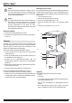
Hinweise zur Entfeuchtungsleistung Bedienung • Das Gerät arbeitet nach dem Einschalten vollautomatisch. • Vermeiden Sie offene Türen und Fenster. Aufstellung Die Entfeuchtungsleistung hängt ab von: • der räumlichen Beschaffenheit • der Raumtemperatur • der relativen Luftfeuchtigkeit Beachten Sie bei der Aufstellung des Gerätes die Mindestabstände Je höher die Raumtemperatur und die relative Luftfeuchtigkeit, zu Wänden und Gegenständen gemäß Kapitel „Technische desto größer ist die Entfeuchtungsleistung.
Inbetriebnahme – Platzieren Sie das Schlauchende des Kondensatablassschlauches oberhalb eines Wasserabflusses. Für größere Distanzen kann auch ein längerer Schlauch des gleichen Typs verwendet werden. Luftfilter einsetzen Kondensatablassschlauch verlegen Hinweis: Bei Auslieferung des Gerätes ist der Kondensatablassschlauch bereits montiert. – Das Gerät kann optional mit einer Kondensatpumpe betrieben werden. Kontaktieren Sie hierzu Ihren TROTEC®Kundenservice. 1.
Gerät einschalten Außerbetriebnahme 1. Vergewissern Sie sich, dass der Kondensatablassschlauch (7) richtig angeschlossen und ordnungsgemäß verlegt ist. Vermeiden Sie Stolperstellen. 2. Stellen Sie sicher, dass der Kondensatablassschlauch (7) nicht geknickt oder verklemmt ist und dass keine Gegenstände auf dem Kondensatablassschlauch (7) stehen. 3. Stellen Sie sicher, dass das Kondensat ordnungsgemäß ablaufen kann. 4. Stecken Sie den Netzstecker in eine ordnungsgemäß abgesicherte Netzsteckdose.
Fehler und Störungen Das Gerät wurde während der Produktion mehrfach auf einwandfreie Funktion geprüft. Sollten dennoch Funktionsstörungen auftreten, so überprüfen Sie das Gerät nach folgender Auflistung. Vorsicht! Um Beschädigungen am Gerät und ein Auslösen der Sicherungen oder der Motorschutzschalter zu vermeiden, warten Sie bei einem Gerätestillstand mindestens 5 Minuten ab, bevor Sie das Gerät erneut einschalten.
Wartung Wartungsintervalle vor jeder Inbetriebnahme Wartungs- und Pflegeintervall Kondensatpumpe, Kondensatwanne bzw. Bautrockner leeren Ansaug- und Ausblasöffnungen auf Verschmutzungen und Fremdkörper prüfen, ggf. reinigen Sichtprüfung des Geräteinneren auf Verschmutzungen Innenreinigung mittels Druckluft Ansauggitter und Luftfilter auf Verschmutzungen und Fremdkörper prüfen, ggf. reinigen bzw.
Tätigkeiten vor Wartungsbeginn Reinigung der Lufteinlässe und des Luftfilters 1. Berühren Sie den Netzstecker nicht mit feuchten oder nassen A. Händen. 2. Ziehen Sie vor allen Arbeiten den Netzstecker! Wartungstätigkeiten an der Elektrik bzw. an der Klimatechnik dürfen nur von Fachbetrieben für Kälte- und Klimatechnik oder von TROTEC® durchgeführt werden. Sichtprüfung des Geräteinneren auf Verschmutzungen 1. Entfernen Sie den Luftfilter (siehe Kapitel „Reinigung der B. Lufteinlässe und des Luftfilters“).
Innenreinigung mittels Druckluft A. B. C.
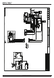
Ersatzteilübersicht und Ersatzteilliste Hauptkomponente Hinweis! Die Positionsnummern der Ersatzteile unterscheiden sich von den in der Bedienungsanleitung verwendeten Positionsnummern der Bauteile. i 40 35 11 41 49 48 3 12 61 31 32 PLAN VIEW TOP 52 42 70 69 67 2 45 6 65 68 66 44 54 O 47 00000.0 h 00000.0 kWh 1 8 5 47 PART VIEW SHOWING COMPRESSOR THERMAL OVERLOAD/ TERMINAL COVER ASSY.
Kondensatwanne Hinweis! Die Positionsnummern der Ersatzteile unterscheiden sich von den in der Bedienungsanleitung verwendeten Positionsnummern der Bauteile. TERMINATE SWITCH WITH BRACKET TO LOOM ASSY SEE FIG 1. 7 2 3 10 4 LOOM ASSY HARD START CAPACITOR IF FITTED TERMINAL BLOCK PART OF LOOM ASSY 1 ON O 1 2 OFF 230V VERSION DUAL VOLTAGE VERSION Nr.
Entsorgung Konformitätserklärung Elektronische Geräte gehören nicht in den Hausmüll, sondern müssen in der Europäischen Union – gemäß Richtlinie 2002/96/EG DES EUROPÄISCHEN PARLAMENTS UND DES RATES vom 27. Januar 2003 über Elektro- und Elektronik-Altgeräte – einer fachgerechten Entsorgung zugeführt werden. Bitte entsorgen Sie dieses Gerät am Ende seiner Verwendung entsprechend der geltenden gesetzlichen Bestimmungen.
Warranty Table of contents The warranty is for 12 months. Damages caused by incorrect use by untrained people or commissioning by unauthorised people are excluded from the warranty. The device complies with the fundamental health and safety requirements of the applicable EU regulations and was tested at the factory for perfect functionality multiple times.
Device depiction and operating elements Information about the device Description of the device 1 This device uses the principle of condensation to automatically dehumidify rooms. To do so, the device can be used in continuous operation. The fan sucks damp room air through the air inlet (2), the air filter (5), the evaporator and to the condenser located behind it. The air is cooled at the cold evaporator until it is below the dew point.
Technical data Parameters Values Model Dehumidifying capacity, max. Dehumidifying capacity (20 °C / 60 % relative humidity) Suitable for room dimensions up to: construction drying or clearing water damages maintaining dryness Operating temperature Working range for relative humidity Volume of airflow, max. Electric connection Power consumption, max.
Cooling circuit diagram PROCESS PORT SOLENOID VALVE COMP L HIGH AIR LIMIT STAT HUMIDISTAT REMOVE LINK IF PUMP FITTED HP SWITCH BREAKS ON PRESSURE RISING (N/C)L LP SWITCH BREAKS ON PRESSURE FALLING CONTROL FUSE CONTACTOR 5 6(NO) HOURS RUN METER A2 2(NO) DELAY TIMER 2 1 1 2 H(N/C) C(COM) C(COM) 1 RUN CAP 1 (N/O) DEFROST THERMOSTAT (COM) 3 4 (N/C) RELAY/HARD START CAP (IF FITTED) R COMPRESSOR S C DEFROST LAMP DEFROST VALVE 2 TEMP FALLING MAKES 1-3 ON FAN MOTOR FAN CAP' S
ISS 1 INITIAL ISSUE TB8 1 2 3 4 R C S COMPRESSOR MOTOR FAN SOLENOID VALVE METER kW HOURS RUN CAP IF FITTED HARD START CAP ON/OFF SWITCH ISOLATOR N TB11 3 2 STAT CONTROL DEFROST PUMP PLUG M/C PLUG IF FITTED WITH PUMP PLUG REMOVE & REPLACE TB10 TB9 DRAWING CHANGE 4 1 TB12 HUMIDISTAT IF FITTED L C/N 1394 DATE 19/01/10 HIGH LEVEL FLOAT SWITCH APPD KW ASPEN PUMP 1 LOW LEVEL FLOAT SWITCH PURGE PUSH BUTTON 2 ASPEN PUMP KIT OPTION 2 4 1 FINISH MATERIAL SOCK
Intended use Only use the device TTK 400 as a mobile industrial dryer for drying Read this manual carefully before starting or using the and dehumidifying room air, while adhering to and following the technical data. device. Store the manual near the device or its site of use! Safety • Do not use the device in potentially explosive rooms. • Do not use the device in atmospheres containing oil, sulphur, chlorine, acid or salt.
Danger! Dangers can occur at the device when it is used by untrained people in an unprofessional or improper way! Observe the personnel qualifications! Danger! A toppling device can cause you injuries! Only slightly tilt the device and move it carefully. If necessary, ask another person to help. For longer distances, transport the device with a fork lift or elevating truck. Never stand below the device when suspended in the air.
Notes regarding the dehumidifying capacity Operation • After being switched on, the device operates fully automatically. • Avoid open doors and windows. The dehumidifying capacity depends on: • the spatial composition of the room • the room temperature • the relative humidity Positioning The higher the room temperature and relative humidity, the higher When positioning the device, observe the minimum distance from the dehumidifying capacity.
Start procedure – Position the end of the condensation drain hose above a water drain. For larger distances, a longer hose of the same type can also be used. Insert air filter Positioning the condensation drain hose Note: The condensation drain hose is already installed when the device is delivered. – The device can also be operated with a condensation pump. Contact TROTEC® customer service if you want this alternative version. 1. Ensure that the condensation drain hose is properly connected 3.
Switching on the device Shut down procedure 1. Ensure that the condensation drain hose (7) has been laid and connected properly. Do not create tripping hazards. 2. Ensure that the condensation drain hose (7) is not bent or jammed and that there are no objects on the condensation drain hose (7). 3. Ensure that the condensation can run off properly. 4. Insert the mains plug into a properly secured mains power socket. Do not create tripping hazards. 5.
Errors and faults The accurate functionality of the device was tested during production a number of times. However, if functionality faults do occur, then check the device according to the following list. Caution! To prevent damages to the device and to prevent the fuse or motor protection switch from tripping, ensure the device is switched off and wait at least 5 minutes before switching the device back on.
Maintenance Maintenance intervals Maintenance and care interval before every start empty the condensation pump, condensation tray and/or construction dryer check air inlets and outlets for dirt and foreign objects and clean if necessary visually check whether the inside of the device is dirty clean the inside with compressed air check air inlet grid and air filter for dirt and foreign objects and clean or replace if necessary replace air filter check for damages check attachment screws carry out a test ru
Activities for before the start of maintenance Cleaning the air inlets and the air filter 1. Do not touch the mains plug with wet or damp hands. 2. Before any work, detach the mains plug! A. Maintenance tasks at the electrical equipment or the air-conditioning technology must only be carried out by specialist companies for cooling and air-conditioning or by TROTEC®. Visual check for dirt in the inside of the device 1. Remove the air filter (see chapter "Cleaning the air inlets and the air filter"). B.
Cleaning the inside with compressed air A. B. C.
Overview and list of spare parts Main components Note! The position numbers of the spare parts differ from those describing the positions of other parts mentioned in this operating manual. i 40 35 11 41 49 48 3 12 61 31 32 PLAN VIEW TOP 52 42 70 69 67 2 45 6 65 68 66 44 54 O 47 00000.0 h 00000.0 kWh 1 8 5 47 PART VIEW SHOWING COMPRESSOR THERMAL OVERLOAD/ TERMINAL COVER ASSY.
Condensation tray Note! The position numbers of the spare parts differ from those describing the positions of other parts mentioned in this operating manual. TERMINATE SWITCH WITH BRACKET TO LOOM ASSY SEE FIG 1. 7 2 3 10 4 LOOM ASSY HARD START CAPACITOR IF FITTED TERMINAL BLOCK PART OF LOOM ASSY 1 ON O 1 2 OFF 230V VERSION DUAL VOLTAGE VERSION No.
Disposal Declaration of conformity In the European Union, electronic equipment must not be treated as domestic waste, but must be disposed of professionally in accordance with Directive 2002/ 96/EC of the European Parliament and Council of 27th January 2003 concerning old electrical and electronic equipment. At the end of its life, please dispose of this instrument in a manner appropriate to the relevant legal requirements.
Garantie Sommaire L'appareil est assorti d'une garantie de 12 mois. Tout sinistre provoqué par une utilisation non appropriée par des personnes non formées ou par la mise en service par des personnes non autorisées est exclu de la garantie. L'appareil répond aux consignes de base d'hygiène et de sécurité des conventions européennes s'y rapportant, et son bon fonctionnement a été contrôlé à plusieurs reprises en usine.
Représentation de l'appareil et éléments de commande Informations sur l'appareil Description de l'appareil 1 L'appareil assure une déshumidification de l'air entièrement automatique et selon le principe de condensation. Il peut alors être utilisé en marche continue. Le ventilateur aspire l’air ambiant humide par l'entrée d'air (2) de l’appareil à travers le filtre à air (5), l’évaporateur et le condensateur qui se trouve derrière l’évaporateur.
Caractéristiques techniques Paramètre Valeur Modèle Capacité de déshumidification, max. Capacité de déshumidification (20 °C / 60 % h.r.) Indiqué pour des pièces d’un volume maximal : déshumidification de chantier et assèchement après dégâts des eaux Déshumidification continue Température de service Humidité relative de référence Débit d'air, max. Alimentation électrique Puissance absorbée, max.
Diagramme circuit de refroidissement PROCESS PORT SOLENOID VALVE COMP L HIGH AIR LIMIT STAT HUMIDISTAT REMOVE LINK IF PUMP FITTED HP SWITCH BREAKS ON PRESSURE RISING (N/C)L LP SWITCH BREAKS ON PRESSURE FALLING CONTROL FUSE CONTACTOR 5 6(NO) HOURS RUN METER A2 2(NO) DELAY TIMER 2 1 1 2 H(N/C) C(COM) C(COM) 1 RUN CAP 1 (N/O) DEFROST THERMOSTAT (COM) 3 4 (N/C) RELAY/HARD START CAP (IF FITTED) R COMPRESSOR S C DEFROST LAMP DEFROST VALVE 2 TEMP FALLING MAKES 1-3 ON FAN MOTOR
ISS 1 INITIAL ISSUE TB8 1 2 3 4 R C S COMPRESSOR MOTOR FAN SOLENOID VALVE METER kW HOURS RUN CAP IF FITTED HARD START CAP ON/OFF SWITCH ISOLATOR N TB11 3 2 STAT CONTROL DEFROST PUMP PLUG M/C PLUG IF FITTED WITH PUMP PLUG REMOVE & REPLACE TB10 TB9 DRAWING CHANGE 4 1 TB12 HUMIDISTAT IF FITTED L C/N 1394 DATE 19/01/10 HIGH LEVEL FLOAT SWITCH APPD KW ASPEN PUMP 1 LOW LEVEL FLOAT SWITCH PURGE PUSH BUTTON 2 ASPEN PUMP KIT OPTION 2 4 1 FINISH MATERIAL SOCK
Utilisation conforme Veuillez utiliser l'appareil TTK 400 exclusivement en tant que désVeuillez lire attentivement le présent manuel avant la mise en humidifcateur industriel mobile pour assécher et pour déshumidiservice/ l'utilisation de l'appareil et conservez-le à proximité fier l'air ambiante selon les caractéristiques techniques.
Déplacer la barre de transport En fonction de vos besoins, vous pouvez basculer la barre de transport au choix dans sa position horizontale ou verticale. Pour déplacer la barre de transport, exécutez les étapes suivantes des deux côtés de l'appareil : 1. Desserrez la vis (15). 2. Retirez les vis (16) et (17). Danger ! 3. Tournez la barre de transport de 90°. Un appareil qui bascule pourrait vous blesser ! Faites 4. Remettez en place les vis (16) et (17) en position inversée.
Indications sur la capacité de déshumidification Utilisation • Après la mise en service, le fonctionnement de l'appareil est entièrement automatique. • Évitez des portes et des fenêtres ouvertes. Installation Lors de l'installation de l'appareil, il faut respecter les distances minimales requises par rapport aux murs et d'autres objets conformément aux indications figurant dans le chapitre « Caractéristiques techniques ».
Mise en service – Placez l'extrémité du flexible de vidage de condensat au dessus d'une évacuation d'eau. Pour des distances plus importantes, vous pourrez également utiliser un flexible plus long du même type. Mettre en place le filtre à air Installer le flexible de vidage de condensat Indication : Lors de sa livraison, l'appareil est déjà doté du flexible de vidage de condensat. – En option, l'appareil peut être utilisé avec une pompe à condensat. Veuillez contacter votre SAV TROTEC®. 1.
Mise en service de l'appareil Mise hors service 1. Veuillez vous assurer que le flexible de vidage de condensat (7) soit correctement raccordé et installé. Attention de ne pas trébucher sur le flexible. 2. Faites en sorte que le flexible de vidage de condensat (7) ne soit pas plié, ni coincé et ne placez pas d'objets sur le flexible de vidage de condensat (7) en question. 3. Veuillez vous assurer que le condensat puisse s'écouler correctement. 4.
Défauts et pannes Dans le cadre de sa production, le bon fonctionnement de l'appareil a été contrôlé à plusieurs reprises. Si, malgré ces contrôles répétitifs, l'appareil présente des dysfonctionnements, il faut le contrôler en se conformant à la liste suivante. Avertissement ! Pour éviter tout endommagement de l'appareil et un déclenchement des fusibles ou des contacteurs moteurs, veuillez attendre au moins 5 minutes en cas d'arrêt de l'appareil avant de le remettre en service.
Maintenance Intervalles de maintenance avant chaque mise en service Intervalle de maintenance et d'entretien Vider la pompe à condensat, le bac de récupération des condensats ou le déshumidificateur de chantier Contrôler les ouvertures d'aspiration et de sortie pour détecter des encrassements ou des corps étrangers, nettoyer le cas échéant Contrôle visuel de l'intérieur de l'appareil pour détecter des encrassements Nettoyage intérieur avec de l'air comprimé Contrôler la grille d'aspiration et le filtre à a
Activités avant de lancer les travaux de maintenance Nettoyage des entrées d'air et du filtre à air 1. Ne touchez jamais la fiche d'alimentation avec des mains huA. mides ou mouillées. 2. Retirez la fiche d'alimentation de la prise secteur avant tout type de travail ! Toute activité de maintenance au niveau du système électrique ou à la climatisation est à dispenser par une entreprise spécialisée dans le domaine du technique frigorifique et climatique ou par la société TROTEC®.
Nettoyage intérieur avec de l'air comprimé A. B. C.
Nomenclature et liste des pièces de rechange Composant principal Indication ! Les numéros de repérage des pièces de rechange sont différents des numéros de repérage des composants utilisés dans le manuel d'utilisation. i 40 35 11 41 49 48 3 12 61 31 32 PLAN VIEW TOP 52 42 70 69 67 2 45 6 65 68 66 44 54 O 47 00000.0 h 00000.0 kWh 1 8 5 47 PART VIEW SHOWING COMPRESSOR THERMAL OVERLOAD/ TERMINAL COVER ASSY.
Bac de condensats Indication ! Les numéros de repérage des pièces de rechange sont différents des numéros de repérage des composants utilisés dans le manuel d'utilisation. TERMINATE SWITCH WITH BRACKET TO LOOM ASSY SEE FIG 1.
Élimination des déchets Déclaration de conformité Les appareils électroniques usagés ne doivent pas être jetés avec les ordures ménagères, mais il faut les éliminer conformément à la directive européenne 2002/96/CE DU PARLEMENT ET DU CONSEIL EUROPEEN du 27 janvier 2003 relative aux déchets d'équipements électriques et électroniques. Veuillez donc éliminer cet appareil à la fin de sa durée de vie conformément aux dispositions de la loi en vigueur.
Garanzia Sommario La garanzia ha una durata di 12 mesi. Sono esclusi dalla garanzia i danni causati da un utilizzo errato di personale non istruito o dalla messa in funzione di persone non autorizzate. L'apparecchio è conforme ai principali requisiti indicati dalle direttive dell'UE concernenti la salute e la sicurezza ed è stato testato più volte dall'azienda per verificarne il funzionamento senza difetti.
Rappresentazione dell'apparecchio ed elementi di comando Informazioni relative all'apparecchio Descrizione dell'apparecchio Con l'aiuto del principio di condensazione, l'apparecchio fornisce una deumidificazione automatica degli ambienti interni. Per fare ciò, l'apparecchio può essere utilizzato nel funzionamento continuo.
Dati tecnici Parametro Valore Modello Potenza del deumidificatore, max. Potenza del deumidificatore (20 °C / 60 % umidità relativa dell'aria) Adatto ad ambienti con dimensioni fino a: Essiccazione delle costruzioni o eliminazione dei danni causati dall'acqua Tenuta dell'asciutto Temperatura di esercizio Area di lavoro della relativa umidità dell'aria Potenza dell'aria, max. Collegamento elettrico Potenza assorbita, max.
Diagramma circuito di raffreddamento PROCESS PORT SOLENOID VALVE COMP L HIGH AIR LIMIT STAT HUMIDISTAT REMOVE LINK IF PUMP FITTED HP SWITCH BREAKS ON PRESSURE RISING (N/C)L LP SWITCH BREAKS ON PRESSURE FALLING CONTROL FUSE CONTACTOR 5 6(NO) HOURS RUN METER A2 2(NO) DELAY TIMER 2 1 1 2 H(N/C) C(COM) C(COM) 1 RUN CAP 1 (N/O) DEFROST THERMOSTAT (COM) 3 4 (N/C) RELAY/HARD START CAP (IF FITTED) R COMPRESSOR S C DEFROST LAMP DEFROST VALVE 2 TEMP FALLING MAKES 1-3 ON FAN MOTOR
ISS 1 INITIAL ISSUE TB8 1 2 3 4 R C S COMPRESSOR MOTOR FAN SOLENOID VALVE METER kW HOURS RUN CAP IF FITTED HARD START CAP ON/OFF SWITCH ISOLATOR N TB11 3 2 STAT CONTROL DEFROST PUMP PLUG M/C PLUG IF FITTED WITH PUMP PLUG REMOVE & REPLACE TB10 TB9 DRAWING CHANGE 4 1 TB12 HUMIDISTAT IF FITTED L C/N 1394 DATE 19/01/10 HIGH LEVEL FLOAT SWITCH APPD KW ASPEN PUMP 1 LOW LEVEL FLOAT SWITCH PURGE PUSH BUTTON 2 ASPEN PUMP KIT OPTION 2 4 1 FINISH MATERIAL SOCK
Uso conforme alla destinazione Utilizzare l'apparecchio TTK 400 esclusivamente come essiccaLeggere presenti istruzioni con attenzione prima della messa tore industriale mobile per asciugare e deumidificare l'aria degli in funzione / dell'utilizzo dell'apparecchio e conservarle ambienti interni, nel rispetto dei dati tecnici.
Pericolo! Da questo apparecchio posso scaturire pericoli, se viene utilizzato in modo non corretto o non conforme alla sua destinazione da persone senza formazione! Tenere conto delle qualifiche del personale! Pericolo! Un apparecchio che si ribalta può provocare lesioni! Inclinare l'apparecchio solo leggermente e maneggiarlo con cautela. Eventualmente chiamare in supporto un'altra persona. In caso di percorsi più lunghi, trasportare l'apparecchio con un carrello elevatore a forca o un carrello elevatore.
Indicazioni relative alla potenza di deumidificazione Comando • Una volta acceso, l'apparecchio procede con funzionamento completamente automatico. • Non aprire porte o finestre.
Messa in funzione – Posizionare l'estremità del tubo di scarico della condensa al di sopra di uno scarico dell'acqua. Per distanze maggiori è possibile anche utilizzare un tubo più lungo dello stesso tipo. Inserimento del filtro dell'aria Posa del tubo di scarico della condensa Avvertenza: Alla consegna dell'apparecchio, il tubo di scarico della condensa è già montato. – L'apparecchio può essere messo in funzione con l'opzione della pompa per condensa. Contattate il vostro servizio clienti TROTEC®. 1.
Accensione dell'apparecchio Messa fuori funzione 1. Assicurarsi che il tubo di scarico della condensa (7) sia stato collegato correttamente e posato a regola d'arte. Evitare i pericoli d'inciampo. 2. Assicurarsi che il tubo di scarico della condensa (7) non sia inflesso o incastrato e che non si trovi alcun oggetto appoggiato sopra al tubo di scarico della condensa (7). 3. Assicurarsi che la condensa possa defluire regolarmente. 4. Inserire la presa di rete in una presa di rete regolarmente protetta.
Errori e disturbi Il funzionamento impeccabile dell'apparecchio è stato controllato più volte durante la sua produzione. Nel caso in cui dovessero, ciononostante, insorgere dei disturbi nel funzionamento, controllare l'apparecchio secondo la seguente lista. Attenzione! Per evitare di danneggiare l'apparecchio e far scattare le sicure o il salvamotore, in caso di arresto dell'apparecchio, attendere almeno 5 minuti prima di riaccendere l'apparecchio.
Manutenzione Intervalli di manutenzione prima di ogni in caso di messa in funzione necessità Intervallo di manutenzione Svuotare la pompa per condensa, la vasca per il condensato ovvero l'essiccatore edile Controllare che non ci sia sporcizia o dei corpi estranei sulle aperture di aspirazione e di scarico, eventualmente pulire Controllo visivo che non ci sia sporcizia nell'interno dell'apparecchio Pulitura degli interni mediante aria compressa Controllare che non ci sia sporcizia o dei corpi estranei sulla
Lavori da eseguire prima dell'inizio della manutenzione Pulitura delle entrate dell'aria e del filtro dell'aria 1. Non toccare la spina di rete con mani umide o bagnate. 2. Estrarre la spina di rete primi di iniziare qualsiasi lavoro! A. I lavori di manutenzione sull'impianto elettrico o sulla tecnica di condizionamento devono essere eseguiti esclusivamente da imprese specializzate in tecnica del freddo e in tecnica di condizionamento dell'aria o dalla TROTEC®.
Pulitura degli interni mediante aria compressa A. B. C.
Prospetto dei componenti ed elenco dei componenti Componenti principale Avvertenza! I numeri di posizione dei componenti si differenzia dai numeri di posizione degli elementi costruttivi utilizzati nelle istruzioni d'uso. i 40 35 11 41 49 48 3 12 61 31 32 PLAN VIEW TOP 52 42 70 69 67 2 45 6 65 68 66 44 54 O 47 00000.0 h 00000.0 kWh 1 8 5 47 PART VIEW SHOWING COMPRESSOR THERMAL OVERLOAD/ TERMINAL COVER ASSY.
Vasca per il condensato Avvertenza! I numeri di posizione dei componenti si differenzia dai numeri di posizione degli elementi costruttivi utilizzati nelle istruzioni d'uso. TERMINATE SWITCH WITH BRACKET TO LOOM ASSY SEE FIG 1. 7 2 3 10 4 LOOM ASSY HARD START CAPACITOR IF FITTED TERMINAL BLOCK PART OF LOOM ASSY 1 ON O 1 2 OFF 230V VERSION DUAL VOLTAGE VERSION N.
Smaltimento Dichiarazione di conformità Gli apparecchi elettronici non devono essere gettati tra i rifiuti domestici, ma all'interno dell'Unione Europea devono essere smaltiti a regola d'arte – come da direttiva 2002/96/CE DEL PARLAMENTO EUROPEO E DEL CONSIGLIO del 27 gennaio 2003 sui vecchi apparecchi elettrici ed elettronici. Al termine del suo utilizzo, vi preghiamo di smaltire questo apparecchio in base alle disposizioni di legge vigenti.
Garantie Inhoudsopgave De garantie is 12 maanden. Schade door bedieningsfouten door niet geïnstrueerd personeel of het in gebruik nemen door niet geautoriseerde personen, is uitgesloten van de garantie. Het apparaat voldoet aan de van toepassing zijnde fundamentele eisen voor wat betreft de veiligheid en gezondheid volgens de EUbepalingen en is in de fabriek meerdere keren getest op een probleemloze werking.
Overzicht van het apparaat en de bedieningselementen Informatie over het apparaat Beschrijving van het apparaat 1 Via het condensatieprincipe zorgt het apparaat voor het automatisch ontvochtigen van ruimten. Hierbij kan het apparaat continu worden gebruikt. De ventilator zuigt de vochtige ruimtelucht aan via luchtinlaat (2) door het luchtfilter (5), de verdamper en de daar achter liggende condensor. Op de koude verdamper wordt de ruimtelucht tot onder het dauwpunt afgekoeld.
Technische gegevens Parameter Waarde Model Ontvochtigingscapaciteit, max. Ontvochtigingscapaciteit (20 °C / 60 % relatieve luchtvochtigheid) Geschikte voor ruimten tot: Bouwdroging of drogen na waterschade Droog houden Bedrijfstemperatuur Werkbereik relatieve luchtvochtigheid Ventilatiecapaciteit, max. Elektrische aansluiting Opgenomen vermogen, max. Opgenomen vermogen, gemiddeld Netzekering gebouwinstallatie Compressor Koudemiddel Koudemiddelhoeveelheid Gewicht Afmetingen (h x d x b) Minimale afstand t.
Schema koelcircuit PROCESS PORT SOLENOID VALVE COMP L HIGH AIR LIMIT STAT HUMIDISTAT REMOVE LINK IF PUMP FITTED HP SWITCH BREAKS ON PRESSURE RISING (N/C)L LP SWITCH BREAKS ON PRESSURE FALLING CONTROL FUSE CONTACTOR 5 6(NO) HOURS RUN METER A2 2(NO) DELAY TIMER 2 1 1 2 H(N/C) C(COM) C(COM) 1 RUN CAP 1 (N/O) DEFROST THERMOSTAT (COM) 3 4 (N/C) RELAY/HARD START CAP (IF FITTED) R COMPRESSOR S C DEFROST LAMP DEFROST VALVE 2 TEMP FALLING MAKES 1-3 ON FAN MOTOR FAN CAP' SOFT S
ISS 1 INITIAL ISSUE TB8 1 2 3 4 R C S COMPRESSOR MOTOR FAN SOLENOID VALVE METER kW HOURS RUN CAP IF FITTED HARD START CAP ON/OFF SWITCH ISOLATOR N TB11 3 2 STAT CONTROL DEFROST PUMP PLUG M/C PLUG IF FITTED WITH PUMP PLUG REMOVE & REPLACE TB10 TB9 DRAWING CHANGE 4 1 TB12 HUMIDISTAT IF FITTED L C/N 1394 DATE 19/01/10 HIGH LEVEL FLOAT SWITCH APPD KW ASPEN PUMP 1 LOW LEVEL FLOAT SWITCH PURGE PUSH BUTTON 2 ASPEN PUMP KIT OPTION 2 4 1 FINISH MATERIAL SOCK
Bedoeld gebruik Gebruik het apparaat TTK 400 uitsluitend als mobiele industriële Lees deze handleiding vóór het in gebruik nemen / gebruik droger voor het drogen en ontvochtigen van de ruimtelucht volvan het apparaat zorgvuldig en bewaar deze in de directe gens de technische gegevens. omgeving van de opstellocatie, resp. het apparaat! Tot het bedoeld gebruik behoren: • het drogen en ontvochtigen van: • Gebruik het apparaat niet in ruimten met explosiegevaar.
Gevaar! Van dit apparaat kunnen gevaren uitgaan als het ondeskundig of niet volgens het bedoeld gebruik wordt gebruikt door niet geïnstrueerde personen! Zorg dat wordt voldaan aan de persoonlijke kwalificaties! Beugel verzetten Afhankelijk van de eisen kunt u de greepbeugel horizontaal of verticaal monteren. Voor het verzetten van de greepbeugel, de volgende stappen uitvoeren aan beide kanten van het apparaat: 1. Schroef (15) iets losdraaien. 2. Verwijder de schroeven (16) en (17). Gevaar! 3.
Opmerkingen m.b.t. de ontvochtigingscapaciteit Bediening • Het apparaat werkt na het inschakelen volautomatisch. • Voorkom open deuren en ramen. Opstellen De ontvochtigingscapaciteit is afhankelijk van: • de aard van de ruimte • de ruimtetemperatuur • de relatieve luchtvochtigheid Houd bij het opstellen van het apparaat rekening met de minimale Hoe hoger de ruimtetemperatuur en de relatieve luchtvochtigheid, afstanden t.o.v.
In gebruik nemen – Plaats het slanguiteinde van de condensafvoerslang boven een waterafvoer. Bij grotere afstanden kan ook een langere slang van hetzelfde type worden gebruikt. Luchtfilter plaatsen Leggen van de condensafvoerslang Opmerking: Bij levering van het apparaat, is de condensafvoerslang al gemonteerd. – Het apparaat kan optioneel ook worden gebruikt met een condenspomp. Neem hiervoor contact op met de TROTEC®klantenservice. 1. Zorg dat de condensafvoerslang correct is aangesloten op het 3.
Apparaat inschakelen Buiten gebruik stellen 1. Zorg dat de condensafvoerslang (7) goed is aangesloten en verlegd. Voorkom struikelgevaar. 2. Zorg dat de condensafvoerslang (7) niet wordt geknikt of ingeklemd en dat geen voorwerpen op de condensafvoerslang (7) staan. 3. Zorg dat het condens goed kan wegstromen. 4. Steek de netstekker in een volgens de voorschriften gezekerd stopcontact. Voorkom struikelgevaar. 5. Verwijder evt.
Defecten en storingen Het apparaat is tijdens de productie meerdere keren op een goede werking getest. Mochten er desondanks storingen ontstaan, controleer het apparaat dan op basis van de volgende lijst. Let op! Om beschadigingen aan het apparaat en het activeren van zekeringen of de motorbeveiligingsschakelaar te voorkomen, bij een stilstaand apparaat minimaal 5 minuten wachten, voordat het apparaat opnieuw wordt ingeschakeld.
Onderhoud Onderhoudsintervallen voor elke keer in gebruik nemen Onderhouds- en verzorgingsinterval Condenspomp, condensopvangbak, resp. bouwdroger legen Aanzuig- en uitblaasopeningen op vervuilingen en vreemde objecten controleren, indien nodig reinigen Visuele controle van het inwendige van het apparaat op vervuilingen Inwendige reiniging met perslucht Aanzuigroosters en luchtfilter op vervuilingen en vreemde objecten controleren, indien nodig reinigen resp.
Werkzaamheden voor aanvang van het onderhoud Reinigen van de luchtinlaten en het luchtfilter 1. Raak de netstekker niet aan met vochtige of natte handen. A. 2. Trek vóór alle werkzaamheden de netstekker uit het stopcontact! Onderhoudswerkzaamheden aan de elektrische, resp. koudetechnische installatie, mogen uitsluitend door gespecialiseerde bedrijven op het gebied van koel- en koudetechniek of door TROTEC® worden uitgevoerd. Visuele controle van het inwendige van het apparaat op vervuilingen B. 1.
Inwendige reiniging met perslucht A. B. C.
Reserveonderdeeloverzicht en reserveonderdeellijst Hoofdcomponenten Opmerking! De positienummers van de reserveonderdelen onderscheiden zich van de in de bedieningshandleiding gebruikte positienummers van de onderdelen. i 40 35 11 41 49 48 3 12 61 31 32 PLAN VIEW TOP 52 42 70 69 67 2 45 6 65 68 66 44 54 O 47 00000.0 h 00000.0 kWh 1 8 5 47 PART VIEW SHOWING COMPRESSOR THERMAL OVERLOAD/ TERMINAL COVER ASSY.
Condensopvangbak Opmerking! De positienummers van de reserveonderdelen onderscheiden zich van de in de bedieningshandleiding gebruikte positienummers van de onderdelen. TERMINATE SWITCH WITH BRACKET TO LOOM ASSY SEE FIG 1. 7 2 3 10 4 LOOM ASSY HARD START CAPACITOR IF FITTED TERMINAL BLOCK PART OF LOOM ASSY 1 ON O 1 2 OFF 230V VERSION DUAL VOLTAGE VERSION Nr.
Recycling Conformiteitsverklaring Elektrische apparaten horen niet in het huisvuil, maar moeten in de Europese Unie – volgens Richtlijn 2002/ 96/EG VAN HET EUROPEES PARLEMENT EN DE RAAD van 27 januari 2003 betreffende afgedankte elektrische en elektronische apparatuur (AEEA) – vakkundig worden gerecycled. Dit apparaat graag aan het eind van de levensduur recyclen volgens de geldende wettelijke bepalingen. In het kader van de EG-Laagspanningsrichtlijn 2006/95/EG en de EG-richtlijn 2004/108/EG m.b.t.
İçindekiler Cihazın kullanım Ömrü ve Garanti Süresi Kullanım kılavuzu hakkında bilgiler ................................. F - 01 Cihazın kullanım Ömrü ve Garanti Süresi......................... F - 01 Cihaz özellikleri ile ilgili tanıtıcı ve temel bilgiler .............. F - 02 Kullanım hatalarına ilişkin bilgiler - Güvenlik ................... F - 06 Taşıma ve Nakliye Sırasında Dikkat Edilecek Hususlar .... F - 07 Bağlantı veya montaj.......................................................
Cihaz özellikleri ile ilgili tanıtıcı ve temel bilgiler Cihazın görünümü ve kumanda elemanları Cihaz açıklaması 1 Cihaz, yoğunlaşma prensibinin yardımıyla odalarda otomatik bir nem giderme işlemi gerçekleştirir. Bunun için cihaz sürekli çalışma modunda kullanılabilir. Fan, nemli oda havasını hava girişinden (2) hava filtresi (5), evaporatör ve arkasında yer alan kondansatör üzerinden emer. Oda havası, soğuk evaporatörde sıcaklığı çiy noktasının altına düşene kadar soğutulur.
Teknik bilgiler Parametre Değer Model Nem alma kapasitesi, maks. Nem alma kapasitesi (20 °C / % 60 bağıl nem) Uygun olduğu maks. oda büyüklükleri: Yapı kurutması veya su hasarlarının giderilmesi Kuru tutma Çalışma sıcaklığı Bağıl nem çalışma aralığı Hava kapasitesi, maks. Elektrik bağlantısı Güç tüketimi, maks.
Soğuk devir daim sisteminin diyagramı PROCESS PORT SOLENOID VALVE COMP L HIGH AIR LIMIT STAT HUMIDISTAT REMOVE LINK IF PUMP FITTED HP SWITCH BREAKS ON PRESSURE RISING (N/C)L LP SWITCH BREAKS ON PRESSURE FALLING CONTROL FUSE CONTACTOR 5 6(NO) HOURS RUN METER A2 2(NO) DELAY TIMER 2 1 1 2 H(N/C) C(COM) C(COM) 1 RUN CAP 1 (N/O) DEFROST THERMOSTAT (COM) 3 4 (N/C) RELAY/HARD START CAP (IF FITTED) R COMPRESSOR S C DEFROST LAMP DEFROST VALVE 2 TEMP FALLING MAKES 1-3 ON FAN MOTOR
ISS 1 INITIAL ISSUE TB8 1 2 3 4 R C S COMPRESSOR MOTOR FAN SOLENOID VALVE METER kW HOURS RUN CAP IF FITTED HARD START CAP ON/OFF SWITCH ISOLATOR N TB11 3 2 STAT CONTROL DEFROST PUMP PLUG M/C PLUG IF FITTED WITH PUMP PLUG REMOVE & REPLACE TB10 TB9 DRAWING CHANGE 4 1 TB12 HUMIDISTAT IF FITTED L C/N 1394 DATE 19/01/10 HIGH LEVEL FLOAT SWITCH APPD KW ASPEN PUMP 1 LOW LEVEL FLOAT SWITCH PURGE PUSH BUTTON 2 ASPEN PUMP KIT OPTION 2 4 1 FINISH MATERIAL SOCK
Usulüne uygun kullanım TTK 400 cihazını sadece oda havasının kurutmak ve nemini almak Bu kılavuzu, cihazı çalıştırmadan/kullanmadan önce için mobil kurutucu olarak ve teknik bilgilere uyarak kullanınız. dikkatlice okuyun ve her zaman kurulum yerinin hemen Usulüne uygun kullanıma dahil olanlar: yakınında veya cihazın üzerinde bulundurunuz! • Aşağıdakilerin kurutulması ve neminin alınması: • Cihazı, patlama tehlikesi bulunan alanlarda çalıştırmayınız.
Tehlike! Eğitimsiz kişiler tarafından amacına veya usulüne uygun olmayan şekilde kullanılması durumunda bu cihaz çeşitli tehlikelere neden olabilir! Personel niteliklerine dikkat ediniz! Tutamaklı kolun yerinin değiştirilmesi Gerekliliklere bağlı olarak, tutamaklı kolu yatay veya dikey olarak monte edebilirsiniz. Tutamaklı kolun yerini değiştirmek için, cihazın iki tarafında aşağıdaki adımları uygulayınız: 1. Cıvatayı (15) gevşetiniz. 2. Cıvataları (16) ve (17) sökünü. Tehlike! 3.
Bağlantı veya montaj Kullanım • Cihaz, çalıştırıldıktan sonra tam otomatik şekilde çalışır. • Kapıları ve pencereleri açık tutmayınız. Nem alma kapasitesiyle ilgili uyarılar Nem alma kapasitesi şunlara bağlıdır: • Cihazın bulunduğu alanın özellikleri • Oda sıcaklığı Kurulum Cihazın kurulumu sırasında, “Teknik bilgiler” bölümü uyarınca • Bağıl nem duvarlarla ve nesnelerle arasında bırakılacak minimum mesafelere dikkat ediniz.
Devreye alma – Kondensat tahliye hortumunun ucunu bir su giderinin üzerine yerleştiriniz. Büyük mesafeler için, aynı tipte daha uzun bir hortum da kullanılabilir. Hava filtresini yerleştirme Kondensat tahliye hortumunun döşenmesi Uyarı: Cihaz teslim edilirken kondensat tahliye hortumu monte edilmiş durumdadır. – Cihaz, opsiyonel olarak bir kondensat pompasıyla çalıştırılabilir. Bu konuda TROTEC® müşteri servisiyle temas kurunuz. 3. Kondensat tahliye hortumunun sürekli bir eğime sahip olması1.
Cihazın çalıştırılması Devre dışı bırakma 1. Kondensat tahliye hortumunun (7) doğru bağlandığından ve kurallara uygun şekilde döşendiğinden emin olunuz. Takılıp düşme yerlerinin oluşmamasını sağlayınız. 2. Kondensat tahliye hortumunun (7) bükülmemiş veya sıkışmamış olduğundan ve kondensat tahliye hortumunun (7) üzerine hiçbir nesnenin durmadığından emin olunuz. 3. Kondensatın düzgün şekilde dışarı akabileceğinden emin olunuz. 4. Elektrik fişini düzgün bir şekilde topraklanmış prize takınız.
Hatalar ve arızalar Cihaz, üretim sırasında sorunsuz bir şekilde çalışma açısından defalarca kontrol edilmiştir. Buna rağmen arızalar ortaya çıkarsa cihazı aşağıdaki listeye göre kontrol ediniz. Dikkat! Cihazda hasarlar oluşmasını ve sigortaların veya motor koruma şalterlerinin devreye girmesini önlemek için, cihaz durduktan sonra cihazı tekrar çalıştırmadan önce en az 5 dakika bekleyiniz. Cihaz çalışıyor ama kondensat oluşmuyor: • Kondensat tahliye hortumunun doğru oturup oturmadığını kontrol ediniz.
Periyodik bakım ile ilgili bilgiler Bakım aralıkları Her çalıştırma öncesinde Bakım ve koruma aralığı Kondensat pompası, kondensat teknesi veya yapı kurutucusunu boşaltınız Emme ve dışarı üfleme açıklıklarını kirlenme ve yabancı cisim açısından kontrol ediniz, gerekiyorsa temizleyiniz Cihazın iç kısmının kirlenip kirlenmediğini görsel olarak kontrol ediniz Basınçlı havayla iç temizlik Emme ızgarası ve hava filtresini kirlenme ve yabancı cisim açısından kontrol ediniz, gerekiyorsa temizleyiniz veya değiştir
Kullanıcının kendi yapabileceği bakım, onarım veya ürünün temizliğine ilişkin bilgiler Hava girişlerinin ve hava filtresinin temizlenmesi A. Bakıma başlanmadan önce yapılacak işlemler 1. Elektrik fişine nemli ya da ıslak elle dokunmayınız. 2. Tüm çalışmalardan önce elektrik fişini çıkartınız! Elektrik sistemi veya iklimlendirme teknolojisindeki bakım işlemleri, sadece soğutma ve iklimlendirme teknolojisi konusunda uzman şirketler veya TROTEC® tarafından gerçekleştirilmelidir.
Basınçlı havayla iç temizlik A. Bakım, Onarım ve Kullanımda Uyulması Gereken kurallar Elektrik sistemi veya iklimlendirme teknolojisindeki bakım işlemleri, sadece soğutma ve iklimlendirme teknolojisi konusunda uzman şirketler veya TROTEC® tarafından gerçekleştirilmelidir. B. C.
Yedek parçalara genel bakış ve yedek parça listesi Ana bileşenler Uyarı! Yedek parçaların pozisyon numaraları, kullanım kılavuzunda parçalar için kullanılan pozisyon numaralarından farklıdır. i 40 35 11 41 49 48 3 12 61 31 32 PLAN VIEW TOP 52 42 70 69 67 2 45 6 65 68 66 44 54 O 47 00000.0 h 00000.0 kWh 1 8 5 47 PART VIEW SHOWING COMPRESSOR THERMAL OVERLOAD/ TERMINAL COVER ASSY.
Kondensat teknesi Uyarı! Yedek parçaların pozisyon numaraları, kullanım kılavuzunda parçalar için kullanılan pozisyon numaralarından farklıdır. TERMINATE SWITCH WITH BRACKET TO LOOM ASSY SEE FIG 1. 7 2 3 10 4 LOOM ASSY HARD START CAPACITOR IF FITTED TERMINAL BLOCK PART OF LOOM ASSY 1 ON O 1 2 OFF 230V VERSION DUAL VOLTAGE VERSION No.
Servis istasyonları Aşağıdaki bilgiler sadece Türkiye için geçerlidir: Trotec End. Ürünleri Tic.Ltd.Şti. Barbaros Cad. E4 Ada B145 Blok No:61 Giyimkent-Esenler-İstanbul Tel: 0212 438 56 55 Üretici ve ithalatçı firmanın ünvanı, adres ve telefon numarası İthalatçı (sadece Türkiye için geçerlidir): Trotec Endüstri Ürünleri Tic.Ltd.Şti. Turgut Reis Mh.Barbaros Cad.E4 Ada B145 Blok No:61 Giyimkent - Esenler - İstanbul Tel.: 0212 438 56 55 Faks: 0212 438 56 51 Üretici: Trotec GmbH & Co. KG Grebbener Str.
Kullanım sırasında insan veya çevre sağlığına tehlikeli veya zararlı olabilecek durumlara ilişkin uyarılar Elektronik cihazlar evsel atık değildir ve Türkiye'de, elektrikli ve elektronik cihazlar hakkındaki Elektrikli ve Elektronik Teçhizat Atıkları Direktifi'ne (EETA) göre uzman bir tasfiye merkezine gönderilmelidir. Kullandıktan sonra lütfen bu cihazı geçerli yasal düzenlemelere uygun şekilde tasfiye ediniz. Cihaz çevre dostu ve ozon açısından nötr bir soğutucu gazla çalıştırılır (bkz.
TROTEC® GmbH & Co. KG • Grebbener Straße 7 • D-52525 Heinsberg Tel.: +49 2452 962-400 • Fax: +49 2452 962-200 www.trotec.com • E-Mail: info@trotec.