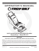
Safety • Assembly • Operation • Maintenance • Troubleshooting • Parts Lists • Warranty OPERATOR’S MANUAL Self Propelled Yard Vacuum/Chipper/Shredder/ Vacuum/Hose — Model 070 / 071 IMPORTANT READ SAFETY RULES AND INSTRUCTIONS CAREFULLY BEFORE OPERATION Warning: This unit is equipped with an internal combustion engine and should not be used on or near any unimproved forest-covered, brushcovered or grass-covered land unless the engine’s exhaust system is equipped with a spark arrester meeting applicable loca
This Operator’s Manual is an important part of your new yard vacuum. It will help you assemble, prepare and maintain the unit for best performance. Please read and understand what it says. Table of Contents Customer Support............................................... 2 Safety Labels....................................................... 3 Safe Operation Practices.................................... 4 Setting Up Your Yard Vacuum............................. 6 Operating Your Yard Vacuum...................
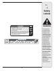
1 Safety Labels $!.'%2 4/ !6/)$ 3%2)/53 ).*529 s 2%!$ /0%2!4/2g3 -!.5!, s +%%0 (!.$3 /54 /& ).,%4 !.$ $)3#(!2'% /0%.).'3 7(),% -!#().% )3 25..).' 2/4!4).' ",!$%3 !2% ).3)$% s 452. %.').% /&& !.$ !,,/7 )-0%,,%2 4/ #/-% 4/ #/-0,%4% 34/0 "%&/2% 2%-/6).' "!' s $/ ./4 !44%-04 4/ #,%!2 ! #,/' /2 *!- 7)4( 4(% %.').% 25..).' s $/ ./4 /0%2!4% 5.)4 7)4(/54 "!' /2 /04)/.!, ",/7%2 #(54% ). 0,!#% s $/./434!.$/27!,+).&2/.4/&",/7%2#(54%/2!)-)4!4"934!.$%23 /"*%#43 4(2/7. /54 /& $)3#(!2'% #!. #!53% 0%23/.!, ).
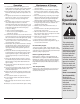
2 Safe Operation Practices WARNING This symbol points out important safety instructions which, if not followed, could endanger the personal safety and/or property of yourself and others. Read and follow all instructions in this manual before attempting to operate this machine. Failure to comply with these instructions may result in personal injury. When you see this symbol.
Operation Maintenance & Storage 1. Do not put hands and feet near rotating parts or in the feeding chambers and discharge opening. Contact with the rotating impeller can amputate fingers, hands, and feet. 2. Before starting the machine, make sure the chipper chute, feed intake, and cutting chamber are empty and free of all debris. 3.
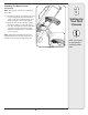
3 IMPORTANT: This unit is shipped without gasoline or oil in the engine. Be certain to service engine with gasoline and oil as instructed in the separate engine manual before operating your machine. Upper Handle Drive Control Speed Control Wing Nut Upper Hose Handle Bracket Setting Up Your Yard Vacuum NOTE: Reference to right and left hand side of the Yard Vacuum is observed from the operating position.
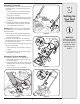
3 Attaching The Handle 1. Remove the hairpin clips from the handle brackets and remove the carriage screws and wing nuts from the lower handle. a. Place the bottom holes in lower handle over the pins on the handle brackets and secure with hairpin clips. See Figure 2. b. Insert carriage screws through upper hole in lower handle from the inside and secure with wing nuts. See Figure 2. Setting Up Your Yard Vacuum " 2. a. Unfold the upper handle until it aligns with lower handle.
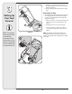
3 Setting Up Your Yard Vacuum 6. a. Snap the hose handle first into the upper hose handle bracket and then into the lower hose handle bracket. See Figure 6. b. Lay hose tubing on hanger bracket next to chipper chute. Attaching The Bag 7. Grasp bag handle with one hand and slide locking rod on mounting bracket with other hand toward engine. Use the end of mounting bracket as leverage when sliding the locking rod. A a.
3 Attaching The Blower Chute (If Equipped) NOTE: The bag must be removed before installing the blower chute. 8. a. Grasp blower chute with one hand and slide locking rod on mounting bracket with other hand toward engine. Use the end of mounting bracket as leverage when sliding the locking rod. See Figure 8. b. Slip blower chute over rim of discharge opening and release locking rod to secure chute in place. c. Raise the nozzle height to the highest setting when using the blower chute.
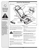
4 Know Your Yard Vacuum Drive Control Starter Handle Speed Control Bag Operating Your Yard Vacuum Throttle Control Choke Control Bag Handle Oil Fill Gasoline Fill Hose Handle Hose Assembly Chipper Chute WARNING The operation of any chipper shredder can result in foreign objects being thrown into the eyes, which can damage your eyes severely. Always wear the safety glasses provided with this unit or eye shields while operating or while performing any adjustments or repairs.
Starting Engine Hose Assembly Used as an alternative to the nozzle to vacuum yard waste such as leaves or pine needles in hard to reach places. See Figure 9. 1. Attach spark plug wire to spark plug. Make certain the metal cap on the end of the spark plug is fastened securely over the metal tip on the spark plug. Nozzle/ Hose Vac Lever The nozzle/hose vac handle is located on top of the nozzle. Use it to switch vacuum suction between the nozzle and the hose assembly. 2.
To Empty Bag 4 B Operating Your Yard Vacuum D 1. a. Unhook bag straps from the lower handle. b. Unsnap bag clip from the top of lower handle. See Figure 10. c. Grasp bag handle with one hand and pull lock rod on mounting bracket with other hand toward engine to release. d. Lift bag off back of unit. 2. Twist the two buttons on the back of the bag to unlock and empty contents. See Figure 11. Hold bag handle and bag clip while emptying the contents. 3.
Yard waste such as leaves and pine needles can be vacuumed up through the nozzle for shredding. After material has been shredded by the flail blades on the impeller assembly, it will be discharged into catcher bag or through blower chute. Do not attempt to shred or chip any material other than vegetation found in a normal yard (i.e. branches, leaves, twigs, etc.) Avoid fibrous plants such as tomato vines until they are thoroughly dried out.
WARNING: Always stop engine and disconnect spark plug wire before cleaning, lubricating or doing any kind of maintenance on your machine. 5 Lubrication Maintaining Your Yard Vacuum 2. Nozzle height adjustment levers: Lubricate the pivot points of the nozzle height adjustment levers once a season with light oil. Refer to Figure 9 on page 10. 3. Locking Rod: Lubricate the locking rod with light oil to ease the application of attaching on or removing bag or blower chute.
Drive Control Cable Adjustment 5 Adjust the drive control cable if the yard vacuum does not self propel with the drive control engaged, or if the unit hesitates while the engine maintains the same speed after approximately 20 hours of use. To move the z-fitting of the drive control cable from its factory set position in the front hole of the drive control to the rear hole, proceed as follows: 1. a. Push the right side of the control out of the right hole in the upper handle. See Figure 15A. b.
Sharpening Or Replacing Chipper Blade 5 NOTE: When tipping the unit, empty the oil and fuel tank and keep engine spark plug side up. 1. Disconnect and ground the spark plug wire to retaining post. 2. Remove hose assembly and bag assembly. Maintaining Your Yard Vacuum 3. Remove the three hex cap screws holding the hose hanger bracket and chipper chute to the upper housing. See Figure 19. 4. Remove the front hubcaps, flange lock nuts, front wheels, and wave washers that attach to the pivot arm assemblies.
9. Using a 3/16” allen wrench, remove the flat head cap screws that hold the chipper blade to the impeller. These screws are accessible through the opening created when the chipper chute was removed earlier. See Figure 23. &LAT (EAD #AP 3CREWS 10. The nuts on the flat head cap screws can be reached from underneath using a 1/2-inch socket, universal, and extension. See Figure 24. 5 Maintaining Your Yard Vacuum 11. Replace or sharpen chipper blade.
6 Problem Engine fails to start Trouble Shooting Cause 1. Throttle lever not in correct starting position. 1. Move throttle lever to FAST or START position. 2. Spark plug wire disconnected. 2. Connect wire to spark plug. 3. Choke not in CHOKE position (if equipped). 3. Move choke lever to CHOKE position. 4. Fuel tank empty or stale fuel. 4. Fill tank with clean, fresh gasoline. 5. Engine not primed (if equipped). 5. Prime engine as instructed in Engine Manual. 6. Faulty spark plug. 6.
NOTES: Use this page to make notes and write down important information. For parts and/or accessories please call 1-866-840-6483, or 1-330-558-7220. www.troybilt.
Model 070 / 071 2 28 66 39 15 27 16 5 B 3 14 71 24 4 43 78 77 45 25 40 9 14 76 42 8 29 80 69 7 6 42 75 79 10 74 26 11 A 64 65 13 15 19 B 48 15 20 18 44 73 46 50 68 55 41 6 72 23 82 58 51 30 22 49 54 70 81 A 12 53 16 17 52 57 59 61 35 65 62 52 31 33 56 65 67 60 63 32 36 34 37 20 38 47 21
Ref. Part No. Description Ref. Part No. Description 1. 736-0451 Saddle Washer, .320 x.93 43. 710-1650 Shoulder Screw, #12-24 x .30 x .46 2. 749-04163 Upper Handle 44. 710-1220 Screw, #12-16 x .750 3. 720-0279 Knob 45. 711-04245 Impeller Hub 4. 710-1205 Eye Bolt 46. 715-0221 Dowel Pin 5. 781-1056 Upper Handle Bracket 47. 781-04082 Front Wheel Support Brace 6. 710-0726 Hex Cap Screw 5/16-12 x.750 48. 781-04081 Rear Wheel Support Brace 7. 720-04072 Star Knob 49.
Models 070 / 071 34 37 35 36 38 49 39 40 1 51 42 41 43 47 32 44 49 45 27 28 B 46 48 33 11 2 3 4 14 11 10 9 7 8 30 B 12 5 29 31 15 17 18 6 21 22 A A 23 13 50 24 25 20 19 26 22 16
Ref. Part No. Description Ref. Part No. Description 1. 664-04031 Bag Assembly 27. 664-04029 Bag 2. 681-0154 Screen Assembly 28. 631-0083 Chute Assembly 3. 710-1054 Hex Screw 5/16-24 x 1.0 29. 736-0247 Flat Washer.375 ID x 1.25 OD 4. 781-0490 Chipper Blade 30. 736-0217 Lock Washer 3/8 5. 781-0735 Pin Clip 31. 710-1273 Hex Cap Screw, 3/8-24 x 2.75 6. 719-0329 Flail 32. 631-04118 Engine Spacer Assembly 7. 715-0166 Spiral Pin 33. 710-1008 Screw, 3/8-16 x 1.875 8.
MANUFACTURER’S LIMITED WARRANTY FOR The limited warranty set forth below is given by Troy-Bilt LLC with respect to new merchandise purchased and used in the United States and/or its territories and possessions, and by MTD Products Limited with respect to new merchandise purchased and used in Canada and/or its territories and possessions (either entity respectively, “Troy-Bilt”).