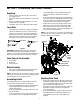
Operator’s Manual Snow Thrower Model 10030 IMPORTANT: Read safety rules and instructions carefully before operating equipment. Warning: This unit is equipped with an internal combustion engine and should not be used on or near any unimproved forestcovered, brush-covered or grass-covered land unless the engine’s exhaust system is equipped with a spark arrester meeting applicable local or state laws (if any). If a spark arrester is used, it should be maintained in effective working order by the operator.
TABLE OF CONTENTS Content Page Important Safe Operation Practices ...................................................................................3 Assembling Your Snow Thrower ........................................................................................5 Know Your Snow Thrower .................................................................................................7 Operating Your Snow Thrower...........................................................................................
SECTION 1: IMPORTANT SAFE OPERATION PRACTICES WARNING: This symbol points out important safety instructions which, if not followed, could endanger the personal safety and/or property of yourself and others. Read and follow all instructions in this manual before attempting to operate this machine. Failure to comply with these instructions may result in personal injury. When you see this symbol—heed its warning.
5. 6. 7. 8. 9. 10. 11. 12. 13. 14. 15. 16. 17. 18. 19. 20. telephone 1-800-800-7310 for assistance and the name of your nearest servicing dealer. Never run an engine indoors or in a poorly ventilated area. Engine exhaust contains carbon monoxide, an odorless and deadly gas. Do not operate machine while under the influence of alcohol or drugs. Muffler and engine become hot and can cause a burn. Do not touch. Exercise extreme caution when operating on or crossing gravel surfaces.
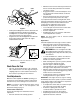
SECTION 2: ASSEMBLING YOUR SNOW THROWER Unpacking • • • • • Remove staples from the top, sides, and ends of the shipping crate. Set panels aside to avoid tire punctures or personal injury. Remove and discard plastic bag that covers unit. Roll the unit out of the crate. Check the crate for loose parts before discarding. • • Loose Parts • The augers are secured to the auger shaft with two shear bolts and hex lock nuts.
• Cable With the traction control released, push the snow thrower forward, then pull it back. The machine should move freely. • Engage the traction control and attempt to move the machine both forward and back, resistance should be felt. • Move the shift lever into the fast reverse (R2) position and repeat the previous two steps.
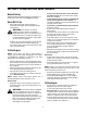
Tire Pressure (Pneumatic Tires) The tires are overinflated for shipping purposes. Auger Control • Check tire pressure. Maintain pressure between 10 and 14 psi. NOTE: If the tire pressure is not equal in all tires, the unit may pull to one side or the other. WARNING: Maximum tire pressure under any circumstance is 30 psi. Equal tire pressure should be maintained at all times.
Traction Control / Auger Control Lock Chute Crank The traction control is located on the right handle. Squeeze the traction control to engage the wheel drive. Release to stop. The chute crank is located on the left hand side of the snow thrower. Use it to change the direction in which snow is thrown. Avoid targetting persons, animals or cars and buildings. This same lever also locks the auger control so you can operate the chute crank without interrupting the snow throwing process.
SECTION 4: OPERATING YOUR SNOW THROWER Before Starting • Read and understand all instructions and warnings on the machine and in this manual before operating. • Gas & Oil Fill-Up • Service the engine with gasoline and oil as instructed in the engine manual shipped with the snow thrower. • • WARNING: Use extreme care when handling gasoline. Gasoline is extremely flammable and the vapors are explosive. Never fuel machine indoors or while the engine is hot or running.
• • Recoil Starter: With engine running, pull starter rope with a rapid, continuous full arm stroke three or four times. Pulling the starter rope will produce a loud clattering sound, which is normal. Move throttle control to “stop” or “off” position. Remove ignition key. Do not turn key. Disconnect the spark plug wire from the spark plug to prevent accidental starting while equipment is unattended. WARNING: The temperature of the muffler and the surrounding areas may exceed 150°F. Avoid these areas.
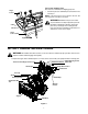
SECTION 5: MAKING ADJUSTMENTS • WARNING: NEVER attempt to clean chute Tip the snow thrower forward, allowing it to rest on the auger housing. See Figure 9. or make any adjustments while engine is running. Frame Cover Shift Rod Ferrule Hairpin Clip Flat Washer Auger Housing Shift Arm Shift Rod Figure 9 • • Figure 8 • • • • • • • Remove the hairpin clip and flat washer from the shift handle under the handle panel. See Figure 8. Place shift lever in sixth (6) position or fastest forward speed.
Skid Shoe Chute Assembly The space between the shave plate and the ground can be adjusted by raising or lowering the skid shoes. • For close snow removal, as when using on a smooth concrete or asphalt driveway, place the skid shoes in the low position. Use the middle or high position when the area to be cleared is uneven. When operating on gravel, always put skid shoes in the high position. See Figure 11.
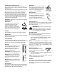
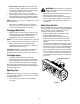
SECTION 6: MAINTAINING YOUR SNOW THROWER Auger Shaft WARNING: Before lubricating, repairing, or • inspecting, disengage all clutch levers and stop engine. Wait until all moving parts have come to a complete stop. Disconnect the spark plug wire and ground it against the engine to prevent unintended starting. At least once a season, remove the shear bolts from the auger shaft and spray lubricant inside the shaft. See Figure 13.
Friction Wheel Rubber Follow the instructions below to check the condition of the friction wheel rubber every 25 hours of operation. • • Chute Crank Spirals • • Lube under chute base Remove the six self-tapping screws from the frame cover underneath the snow thrower. Visually inspect the friction wheel rubber for excessive wear, cracks, or loose fit on the friction wheel drive hub. Also engage the traction control and check if the friction wheel is making contact with friction plate. Refer to Figure 10.
SECTION 7: SERVICING YOUR SNOW THROWER against the skid shoes). Make certain the skid shoes are adjusted to be level. To remove the shave plate, remove the carriage bolts, belleville washers and hex nuts which attach the shave plate to the snow thrower housing.See Figure 17. Reassemble the new shave plate, with heads of carriage bolts to the inside of the housing. Tighten securely. WARNING: Before servicing, repairing, or • inspecting, disengage all clutch levers and stop engine.
Friction Wheel Drive Pulley Auger Pulley Drive Belt Drive Plate Stop Bolt Idler Pulley Idler Pulley Auger Belts Frame Support Bracket Auger Pulley Figure 21 Figure 19 • • • Changing Friction Wheel Rubber Lift the rear auger belt from the auger pulley, and slip the belt between the support bracket and the auger pulley. Repeat for the front auger belt. See Figure 20. Replace both auger drive belts by following instructions in reverse order.
• Shift Rod Assembly Gear Shaft • Pin Sprocket Reassemble the new friction wheel rubber to the friction wheel plates and hub, tightening the six screws in rotation and with equal force. Position the friction wheel assembly up onto the pin of the shift rod assembly, and slide the hex shaft through the friction wheel assembly. Reassemble in reverse order.
SECTION 9: TROUBLESHOOTING Problem Cause Remedy Engine fails to start. 1. 2. 3. 4. 5. 6. 7. Fuel tank empty, or stale fuel. Blocked fuel line. Choke not in ON position Faulty spark plug. Safety key not in ignition switch on engine. Spark plug wire disconnected. Primer button not being used properly. 1. 2. 3. 4. 5. 6. 7. Fill tank with fresh gasoline. Clean the fuel line. Move switch to ON position Clean, adjust gap or replace. Insert the key fully into the switch. Connect spark plug wire.
Safety & Decorative Labels 777D06574 TOUCH 'N TURN STEERING • ALL WHEEL DRIVE • ELECTRIC START • JUST ONE HAND ® OPERATION D06574 777D06563 777D03165 777I22052 777I22049 AUGER CONTROL 777I22053 READ OPERATORS MANUAL BEFORE STARTING. INSERT IGNITION KEY INTO SLOT. MAKE SURE IT SNAPS INTO PLACE. DO NOT TURN KEY. 4 RECOIL STARTER: PUSH PRIMER 2 OR 3 TIMES. ELECTRIC STARTER: DO NOT PRIME. SELECT SPEED REQUIRED. SQUEEZE RIGHT TRACTION CONTROL LEVER TO MOVE. RELEASE TO STOP.
SECTION 10: PARTS LIST FOR MODEL 10030 5 9 29 31 24 25 33 19 36 32 30 17 14 22 6 13 13 18 42 27 1 13 18 22 45 40 41 22 6 43 39 24 22 44 13 24 10 23 45 16 15 11 35 21 28 21 26 38 28 7 7 23 8 10 34 37 20
Model 10030 Ref. No. 1. 2. 3. 4. 5. 6. 7. 8. 9. 10. 11. 12. 13. 14. 15. 16. 17. 18. 19. 20. 21. 22. 23. Part No. 05931A 684-0065 705-5226 710-0451 710-0459A 710-0604A 710-0703 710-0890A 712-0116 712-0324 712-0429 712-0798 712-3010 712-3068 715-0114 731-1379C 732-0611 736-0119 736-0167 736-0169 736-0188 736-0242 736-0463 Ref. No. Part Description Bearing Housing Impeller Assembly Chute Reinforcement Carriage Bolt Hex Bolt 3/8-24 x 1.5” TT Screw 5/16-18 x 0.625” Carriage Screw 1/4-20 x 0.
Model 10030 40 39 64 35 8 45 52 55 41 8 45 47 63 35 50 65 8 8 31 13 37 25 36 5 20 2 31 31 43 33 18 16 8 21 19 12 30 49 22 6 44 13 20 4 14 22 37 17 38 31 36 23 11 29 41 8 25 32 18 33 53 3 32 38 42 24 26 50 8 1 10 12 9 7 30 27 15 8 13 10 45 57 51 10 28 35 10 22 6 59 62 58 59 61 60 22 54 56 16
Model 10030 Ref. No. Part No. 1. 2. 3. 4. 5. 6. 618-0043 618-0044 618-0575 656-0012A 684-0014B 684-0042C 7. 8. 9. 10. 11. 12. 13. 14. 15. 16. 17. 18. 19. 20. 21. 22. 23. 24. 25. 26. 27. 28. 29. 30. 31. 32. 33. 684-0131A 710-0599 710-0809 710-1652 711-1267 711-1268 711-1364 712-0703A 712-0711 712-3017 713-0233 713-0374 713-0413 713-0472 714-0474 714-0474 716-0102 721-0263 732-0209 732-0264 736-0105 736-0142 736-0160 736-0169 736-0351 736-0626 737-0318 Ref. No. Part Description 34. 35. 36. 37. 38. 39.
Model 10030 39 40 A 45 37 42 47 C B L1 F 34 E 43 B C 35 L1 40 44 46 D 41 G L2 36 8 19 5 38 8 A 8 22 13 31 18 23 8 12 A 4 16 10 26 14 24 32 3 29 11 25 15 27 17 30 33 14 2 28 20 6 20 9 7 14 1 24 14 21 Harness Assembly Connector Plugs to: A Alternator lead from engine B, C, L1, L2 Switch and Light 1 and 2 D, E Heated Grips of handles F indicates fuse; G indicates grounding wire.
Model 10030 Ref. No. Part No. 1. 2. 3. 4. 5. 6. 7. 8. 9. 10. 11. 12. 13. 14. 15. 16. 17. 18. 19. 20. 21. 22. 23. 24. 25. 26. 27. 28. 29. 30. 31. 32. 33. 34. 684-0008A 684-0053B 705-5266 710-0449 710-0458 710-0643 710-0788 710-0837 710-1880 710-3015 711-0677 712-0287 712-3068 714-0104 714-0145 720-0201A 720-0284 725-1757 726-0100 736-0119 736-0185 736-0242 736-0270 736-0275 736-0451 741-0475 747-0620A 747-0621 747-0737 749-0951 749-0952A 749-0953A 750-0963 629-04007 35. 36.
Model 10030 30 29 32 33 Supplied on engine 27 34 7 31 10 28 31 17 4 11 20 14 23 26 25 3 8 21 4 23 13 6 15 18 23 1 9 22 12 2 16 5 24 19 26
Model 10030 Ref. No. 1. 2. 3. 4. 5. 6. 7. 8. 9. 10. 11. 12. 13. 14. 15. 16. 17. 18. 19. 20. 21. 22. 23. 24. 25. 26. 27. 28. 29. 30. 31. 32. 33. 34. Part No. Description 05896A 710-1245B 710-0230 710-0627 710-0654A 710-0696 710-1652 710-3005 712-0181 731-1324 732-0710 736-0242 736-0247 736-0270 736-0331 736-0505 Idler Bracket: Drive Clutch Hex Bolt 5/16-24 x .875” Hex Screw 1/4-28 x .50” Hex Screw 5/16-24 x .750” TT Screw 3/8-16 x 1.0” Hex Screw 3/8-24 x .875” TT Screw 1/4-20 x .
Model 10030 Ref. No. 39 34 33 22 29 35 22 6 23 25 30 38 12 36 27 37 22 34 39 26 32 20 24 28 31 30 4 6 33 15 21 6 19 3 10 17 16 6 18 8 10 11 1 2 4 40 13 6 44 41 7 42 9 9 5 5 43 28 Part No. Description 1. 710-04071 Carriage Bolt 5/16-18 x 1.0” 2. 710-0262 Carriage Bolt 5/16-18 x 1.5” 3. 710-0805 Hex Bolt 5/16-18 x 1.5” 4. 710-0896 Hex AB Screw 1/4-14 x .625” 5. 710-3015 Hex Screw 1/4-20 x .75” 6. 712-0429 Hex Lock Nut 7. 712-3027 Hex Flange Lock Nut 8.
MANUFACTURER’S LIMITED WARRANTY FOR: The limited warranty set forth below is given by Troy-Bilt LLC with respect to new merchandise purchased and used in the United States, its possessions and territories. Troy-Bilt LLC warrants this product against defects for a period of two (2) years commencing on the date of original purchase and will, at its option, repair or replace, free of charge, any part found to be defective in materials or workmanship.