Operator’s Manual Two-Stage Snow Thrower Model 1030 Storm IMPORTANT: Read safety rules and instructions carefully before operating equipment. Warning: This unit is equipped with an internal combustion engine and should not be used on or near any unimproved forestcovered, brush-covered or grass-covered land unless the engine’s exhaust system is equipped with a spark arrester meeting applicable local or state laws (if any).
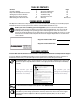
TABLE OF CONTENTS Content Customer Support Important Safe Operation Practices Setting Up Your Snow Thrower Operating Your Snow Thrower Maintaining Your Snow Thrower Content Service & Adjustments Off-Season Storage Troubleshooting Illustrated Parts List Warranty Page 2 3 5 8 12 Page 14 18 19 20 Back Cover FINDING MODEL NUMBER This Operator’s Manual is an important part of your new snow thrower. It will help you assemble, prepare and maintain the unit for best performance.
SECTION 1: IMPORTANT SAFE OPERATIONS PRACTICES WARNING: This symbol points out important safety instructions which, if not followed, could endanger the personal safety and/or property of yourself and others. Read and follow all instructions in this manual before attempting to operate this machine. Failure to comply with these instructions may result in personal injury. When you see this symbol—heed its warning.
Operation unclogging, shut off engine and remain behind handles until all moving parts have stopped completely. 19. Use only attachments and accessories approved by the manufacturer (e.g. wheel weights, tire chains, cabs etc.). 20. If situations occur which are not covered in this manual, use care and good judgment. Contact your dealer or telephone 1-800-520-5520 for assistance and the name of your nearest servicing dealer. 1.
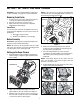
SECTION 1: SETTING UP YOUR SNOW THROWER NOTE: If the connector is not properly assembled, the shift rod will pivot and changing speed or direction of the snow thrower will not be possible. IMPORTANT: This unit is shipped with the engine full of oil. After assembly, see page 9 for fuel and oil details. Removing From Carton 1. Cut the corners of the carton and lay the sides flat on the ground. Remove all packing inserts. 2. Move the snow thrower out of the carton. 3.
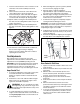
4. While standing in the operator’s position (behind the snow thrower) engage the auger. 5. Allow the auger to remain engaged for approximately ten (10) seconds before releasing the auger control. Repeat this several times. 6. With the engine running in the FAST position and the auger control in the disengaged “up” position, walk to the front of the machine. 7. Confirm that the auger has completely stopped rotating and shows NO signs of motion. 7.
2. Make certain the entire bottom surface of skid shoes are against the ground to avoid uneven wear on the skid shoes. 3. Tighten nuts and bolts securely. 8. If the wheels can still be turned when you engage the drive control, loosen the jam nut on the drive cable and thread the cable in one turn. Recheck the adjustment and repeat if needed. 9. Tighten the jam nut to secure the cable when correct adjustment is reached.
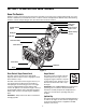
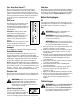
SECTION 2: OPERATING YOUR SNOW THROWER Know The Controls Read this owner’s manual and safety rules before operating your snow thrower. Compare Figure 8 with your snow thrower to familiarize yourself with the location of various controls and adjustments. Maintain safety while learning about the controls and operating the unit. Save this manual for future reference.
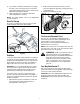
Four- Way Chute Control™ Skid Shoe This four-way control lever is meant to control the direction and distance of snow discharge from the chute. Press the button on the knob and turn it left or right to rotate the chute to the direction that snow will be thrown. Tilt the lever forward to decrease the distance snow will be thrown, and backwards to increase distance. The skid shoe position is determined by the condition of the ground from where snow has to be removed.
Electric Starter 12. When the engine starts, release the starter button and slowly rotate the choke to OFF position. If the engine falters, rotate the choke to FULL and then gradually to OFF. 13. Disconnect the power cord from the receptacle first and then from the switch box on the engine. 14. Allow the engine to warm up for a few minutes because the engine will not develop full power until it reaches operating temperature. Operate the engine at full throttle (FAST) when throwing snow.
Before Stopping and the wheel drive. To stop the auger, both levers must be released. 1. Run engine for a few minutes to help dry off any moisture on engine. 2. Avoid freezing of the starter by following these steps before stopping the snow thrower: To Throw Snow CAUTION: Check the area to be cleared for foreign objects. Remove, if any. Recoil Starter a. With the engine running, pull the starter rope with a rapid, continuous full arm stroke three or four times. 1.
Chute Clean-Out Tool On models so equipped, drift cutters are assembled to the auger housing inverted. Remove the carriage bolts by unthreading the hex nuts which secure them, and reinstall the drift cutters in their proper position before operating the snow thrower. See Figure 9 . The clean-out tool is conveniently fastened to the rear of the auger housing with a mounting clip. Never use your hand to clean a clogged chute. 1. Release both the auger control and the drive/auger control lock. 2.
• • • • • 1. Remove the self-tapping screws from the frame cover underneath the snow thrower. Refer to Figure 15. 2. Visually inspect the friction wheel rubber for excessive wear, cracks, or loose fit on the friction wheel drive hub. 3. Also engage the drive control and check if the friction wheel is making contact with drive plate. If it does not make contact, adjust the drive cable (refer to page17) and recheck the friction wheel. 4. Replace friction wheel rubber if necessary.
SECTION 4: SERVICE & ADJUSTMENT WARNING: Always stop engine, disconnect spark plug wire and move it away from spark plug before performing adjustments or repairs. Always wear safety glasses during operation or while performing any adjustments or repairs. Servicing Augers The augers are secured to the spiral shaft with six shear pins and cotter pins. See Figure 12 . Carriage Bolt Skid Shoe 1. If the augers do not turn, check to see if the pins have sheared. 2. Replace the pins if needed.
A Belt Cover Self-Tapping Screw Self-Tapping Screw Auger Pulley Shoulder Screw B Spring Mounting Bracket Engine Pulley Drive Belt Figure 16 4. Wrap auger belt around the auger pulley. See Figure 16. 5. Re-insert shoulder screw into the mounting bracket and tighten to secure. 6. Wrap auger belt behind the idler. Reattach the spring to the bolt where it was earlier secured. 7. Re-install frame cover and flip the snow thrower back to the operating position. 8. Wrap auger belt around the engine pulley.
4. Back out the stop bolt to create sufficient gap between the friction wheel disc and the drive pulley. Pull the drive belt from around the drive pulley and clear it off the friction wheel disc. See Figure 18. Drive Belt Drive Cover Bolt Friction Wheel Drive Pulley Spacer Stop Bolt Figure 19 6. Holding the friction wheel assembly, slide the hex gear shaft to the right. See Figure 20. The spacer on right side of hex gear shaft may fall. Figure 18 5.
2. With the drive control released, there must be 1/8” clearance between the friction wheel and the drive plate in all positions of the shift lever. 3. With the drive control engaged, the friction wheel must contact the drive plate (Figure 19). 4. If adjustment is necessary, loosen the jam nut on the drive cable and thread the cable in or out as necessary. Tighten the jam nut to secure the cable when correct adjustment is reached. Reassemble the frame cover. 10.
7. Check for correct adjustment before operating the snow thrower. Chute Control Skid Shoe Refer to page 7 for details. Chute Control Once a season or every 25 hours of operation, whichever is earlier, check whether the chute control cables have slackened. If the chute does not rotate fully or its pitch cannot be moved up or down, the chute control cables will have to be adjusted. To adjust these cables, proceed as follows: 1. To tighten cable, loosen the top nut and tighten the bottom nut on the cable.
SECTION 6: TROUBLESHOOTING Problem Cause Engine fails to start. 1. 2. 3. 4. 5. 6. 7. 8. Engine runs erratic. Remedy Fuel tank empty, or stale fuel. Blocked fuel line. Choke not in ON position. Faulty spark plug. Safety key not in ignition switch on engine. Spark plug wire disconnected. Primer button not being used properly. Fuel shut-off valve closed. (If Equipped) 1. Unit running on CHOKE. 2. Blocked fuel line or stale fuel. 3. Water or dirt in fuel system. 4. Carburetor out of adjustment. 1. 2. 3.
SECTION 7: PARTS LIST FOR MODEL 1030 1 10 2 3 4 12 5 6 7 9 14 13 2 55 31 33 8 16 34 15 29 15 17 52 22 19 20 32 18 2 27 24 26 23 25 27 47 15 37 40 33 37 27 39 36 51 2 2 53 41 48 60 58 54 71 28 30 49 50 45 46 70 59 61 35 44 43 42 57 62 56 65 66 67 63 69 68 21 64 20 70
Model 1030 Ref. No. 1. 2. 3. 4. 5. 6. 7. 8. 9. 10. 12. 13. 14. 15. 16. 17. 18. 19. 20. 21. 22. 23. 24. 25. 26. 27. 28. 29. 30. 31. 32. 33. 34. 35. 36. Part No.
Model 1030 1 2 3 4 5 11 6 58 7 8 59 12 61 13 21 60 17 14 9 55 62 10 B 15 A 16 18 22 44 11 19 20 B 23 24 26 43 25 56 27 40 41 A 28 36 29 39 38 31 30 37 32 54 45 33 34 54 46 52 57 42 47 35 48 49 51 53 50 22 22
Model 1030 Ref. No. Part No. Description Ref. No. 1. 2. 3. 4. 5. 6. 7. 8. 9. 10. 11. 12. 13. 14. 15. 16. 17. 18. 19. 20. 21. 22. 23. 24. 25. 26. 27. 28. 29. 30. 31.
Model 1030 74 76 75 1 2 56 73 57 58 60 3 59 55 56 63 54 64 65 66 50 67 48 51 52 55 53 49 5 72 68 1 47 71 69 4 46 7 6 45 8 10 9 11 1 12 18 20 43 13 14 21 22 44 41 61 17 15 19 1 24 25 26 39 38 23 16 42 28 27 29 62 70 36 30 16 31 37 32 34 1 17 35 33 40 1 41 43 42 43A 42C 41A 42H 42A 41B 42I 42B 41C 42J 42K 42D 42E 42F 42G 24 43B 43D 43C 43E 43F
Model 1030 Ref No. 1. 2. 3. 4. 5. 6. 7. 8. 9. 10. 11. 12. 13. 14. 15. 16. 17. 18. — 19. 20. 21. 22. 23. 24. 25. 26. 27. 28. 29. 30. 31. 32. 33. 34. 35. 36. 37. 38. 39. 40. 41. A. B C. 42. A. B. Part No.
Safety & Decorative Labels 777D08376 ? 777D03165 On each handle grip 777 I22378 DRIVE AUGER LOCK OPERATORS VIEW 777I22343 CHUTE DIRECTIONAL CONTROL CHUTE TILT DOWN PUSH BUTTON CHUTE ROTATE LEFT PUSH BUTTON CHUTE ROTATE RIGHT CHUTE TILT UP STARTING INSTRUCTIONS: 1.) INSERT IGNITION KEY AND SNAP IN PLACE. 2.) SET CHOKE AND THROTTLE TO FULL (ON) POSITION. PUSH PRIMER BUTTON 3x. 3.) ROPE START: PULL SLOWLY UNTIL HARDER TO PULL, THEN PULL RAPIDLY TO START. REPEAT PRIMING IF NEEDED.
MANUFACTURER’S LIMITED COMMERCIAL WARRANTY FOR: The limited warranty set forth below is given by Troy-Bilt LLC with respect to new merchandise used for commercial purposes and purchased and used in the United States and/ or its territories and possessions, and by MTD Products Limited with respect to new merchandise purchased and used in Canada and/or its territories and possessions (either entity respectively, “Troy-Bilt”). c. d. e.
MANUFACTURER’S LIMITED WARRANTY FOR: The limited warranty set forth below is given by Troy-Bilt LLC with respect to new merchandise purchased and used in the United States and/or its territories and possessions, and by MTD Products Limited with respect to new merchandise purchased and used in Canada and/or its territories and possessions (either entity respectively, “Troy-Bilt”).