Operator’s Manual Snow Thrower Model 10530—Polar Blast IMPORTANT: READ SAFETY RULES AND INSTRUCTIONS CAREFULLY WARNING: This unit is equipped with an internal combustion engine and should not be used on or near any unimproved forestcovered, brush-covered or grass-covered land unless the engine’s exhaust system is equipped with a spark arrester meeting applicable local or state laws (if any). If a spark arrester is used, it should be maintained in effective working order by the operator.
TABLE OF CONTENTS Content Page Important Safe Operation Practices ........................................................................ 3 Loose Parts & Hardware Pack................................................................................. 5 Assembling Your Snow Thrower ............................................................................. 7 Know Your Snow Thrower ....................................................................................... 10 Operating Your Snow Thrower .......
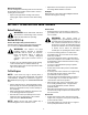
SECTION 1: IMPORTANT SAFE OPERATION PRACTICES This symbol points out important safety instructions, which if not followed, could endanger the personal safety and/or property of yourself and others. Read and follow all instructions in this manual before attempting to operate this machine. Failure to comply with these instructions may result in personal injury. When you see this symbol—heed its warning.
. 5. 6. 7. 8. 9. 10. 11. 12. 13. 14. 15. 16. 17. 18. 19. 20. Contact your dealer or telephone 1 (866) 840-6483 for assistance and the name of your nearest servicing dealer. Never operate with a missing or damaged discharge chute. Keep all safety devices in place and working. Never run an engine indoors or in a poorly ventilated area. Engine exhaust contains carbon monoxide, an odorless and deadly gas. Do not operate machine while under the influence of alcohol or drugs.
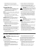
SECTION 2: ASSEMBLING YOUR SNOW THROWER NOTE: All references to right or left side of the snow thrower are determined from behind the unit in the operating position. The “operator’s position” is defined as standing directly behind the snow thrower, facing the handle panel. Loose Parts • The augers are secured to the auger shaft with two shear bolts and hex lock nuts. If you hit a foreign object or ice jam, the snow thrower is designed so that the bolts may shear.
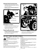
Attaching Chute Directional Control • • Cable Guide Discharge Chute Remove the hairpin clip from the upper rod and slide the upper rod through the bracket and into the lower rod. See Figure 4. Align the two holes on both chute cranks and insert the hairpin clip removed earlier, through these holes. See Figure 4.
Traction Control / Auger Control Lock Shift Lever Chute Tilt Control Headlights Discharge Chute Auger Control Fuel Tank Chute Directional Control Chute Clean-out Tool Left Wheel Steering Control (Right Control Not Visible) Electric Starter Button Primer Choke Safety Ignition Key Auger Switch Box Recoil Starter Handle Throttle Control Skid Shoe Figure 7 Shift Lever Auger Control The shift lever is located in the center of the handle panel and is used to determine ground speed and direction
Wheel Steering Controls • The left and right wheel steering controls are located on the underside of the handles and are used to assist in steering the snow thrower. Headlights • Operate the snow thrower in open areas until becoming familiar with these controls. When properly connected, both headlights illuminate whenever the engine is running. Squeeze the right wheel steering control when turning right; squeeze the left control when turning left.
NOTE: Always cover vent hole in primer button when • pushing. Additional priming may be necessary for first start if temperature is below 15°F. • • • Grasp starter handle and pull rope out slowly, until it pulls slightly harder. Let rope rewind slowly. Pull starter handle rapidly. Do not allow handle to snap back. Allow it to rewind slowly while keeping a firm hold on the starter handle. Repeat the previous steps until engine starts.
• Repeat Auger Control Test to verify proper adjustment has been achieved. Repeat the previous steps to provide more slack in the cable, in necessary. 2. Stop the engine by removing the ignition key. 3. Remove the clean-out tool from the clip which secures it to the rear of the auger housing. 4. Use the shovel-shaped end of the clean-out tool to remove any snow and ice in the discharge chute.
• • Thread the lock nut outward (down the coupler) three full turns to provide more slack in the cable and reattach the spring to the bracket. • Check the adjustment of the traction control as instructed earlier. Repeat the previous steps to provide more slack in the cable, in necessary. If you are uncertain that you have reached the correct adjustment, proceed as follows: • • • Remove the hairpin clip and flat washer from the shift handle under the handle panel.
WARNING: Maximum tire pressure under any circumstance is 30 psi. Equal tire pressure should be maintained at all times. Excessive pressure (over 30 psi) when seating beads may cause tire/rim assembly to burst with force sufficient to cause serious injury Skid Shoe Adjustment The space between the shave plate and the ground can be adjusted by raising or lowering the skid shoes. High For close snow removal, as when using on a smooth concrete or asphalt driveway, place the skid shoes in the low position.
Discharge Chute The base of the discharge chute and the spirals on the chute crank should be lubricated at least every 25 hours of use. Apply the lubricant under the base of the chute and where the spirals contact the discharge chute. See Figure 14. Handle Panel Chute Crank Spirals Control Rods Lube Cams Here Figure 15 Engine Refer to the separate engine manual packed with your unit for all engine lubrication instructions.
SECTION 7: SERVICING YOUR SNOW THROWER WARNING: Before servicing, repairing, or • inspecting, disengage all clutch levers and stop engine. Wait until all moving parts have come to a complete stop. Disconnect spark plug wire and ground it against the engine to prevent unintended starting. • Augers • The augers are secured to the spiral shaft with two shear bolts and hex lock nuts. If you hit a foreign object or ice jam, the snow thrower is designed so that the bolts may shear. See Figure 16.
Auger Belt Idler Pulley Auger Pulley Brake Bracket Assembly Engine Pulley Shoulder Bolt Figure 18 • • Remove the cotter pin and washer from the ferrule in order to disconnect the auger idler rod from the brake bracket assembly. See Figure 19. Slip the auger control belt (the front belt) off the engine pulley. Engine Pulley Figure 20 • Reassemble the belt cover and chute directional control.
• • • • • Secure the two halves with the two bolts and lock washers removed earlier. Refer to Figure 18. Attach the “Z” fitting of the cable into the brake bracket assembly. Refer to Figure 19. Slip the auger control belt over engine pulley. Insert ferrule on auger idler rod into bracket assembly and secure with flat washer and cotter pin. Reassemble the large shoulder bolt and lock washer as shown in Figure 18. Reassemble belt cover and chute crank.
Off-season Storage • NOTE: When storing any type of power equipment in an unventilated or metal storage shed, care should be taken to rust proof the equipment. Using a light oil or silicone, coat the equipment, especially any chains, springs, bearings and cables. WARNING: Never store engine with fuel in tank indoors or in poorly ventilated areas, where fuel fumes may reach an open flame, spark or pilot light as on a furnace, water heater, clothes dryer or other gas appliance.
SECTION 9: MODEL 10530 PARTS LIST 59 47 57 43 60 16 21 40 25 8 42 14 31 25 8 7 5 1 14 21 25 55 25 27 13 14 18 48 3 26 34 17 45 54 53 9 50 25 14 34 26 32 13 44 56 52 46 22 51 5 13 33 49 41 REAR VIEW 58 11 25 14 5 2 35 19 28 6 12 15 36 38 37 29 20 24 25 13 29 30 10 23 39 4 18 13
Model 10530 Ref. No. 1. 2. 3. 4. 5. 6. 7. 8. 9. 10. 11. 12. 13. 14. 15. 16. 17. 18. 19. 20. 21. 22. 23. 24. 25. 26. 27. 28. 30. 31. Part No. 05244A 618-0281A 684-0090A 710-0371 710-0451 710-0459A 710-0528 710-0604A 710-0891 711-0640 711-0677 712-0116 712-0429 712-3010 714-0104 714-0126 714-0135 715-0118 731-1696 732-0858 736-0119 736-0159 736-0169 736-0174 736-0242 736-0250 736-0271 736-3008 738-0281 741-04024 Ref. No.
Model 10530 18 12 63 18 6 80 60 8 17 79 76 68 83 54 68 18 9 16 26 50 16 62 77 53 15 66 61 16 49 4 18 24 35 36 45 42 49 47 56 47 13 30 32 65 3 39 42 67 27 75 23 22 33 69 34 14 33 51 2 22 61 21 29 19 55 30 72 66 62 61 48 27 58 15 47 29 13 19 52 49 56 18 38 20 70 40 82 43 7 44 28 59 31 20 26 51 37 57 20 54 50 16 71 64 47 10 45 35 5 1 78 81 45 41 48 19 73 11 60 77
Model 10530 Ref. No. 1. 2. 3. 4. 5. 6. 7. 8. 9. 10. 11. 12. 13. 14. 15. 16. 17. 18. 19. 20. 21. 22. 23. 24. 25. 26. 27. 28. 29. 30. 31. 32. 33. 34. 35. 36. 37. 38. 39. 40. 41. 42. 43. 44. 45. Part No.
Model 10530 39 43 36 8 37 43 A 35 33 32 A 9 22 11 6 42 38 12 44 40 11 29 34 7 22 24 3 21 13 10 1 15 23 28 A 27 13 9 21 32 31 A 15 5 35 33 1 17 19 16 21 26 4 19 18 6 7 23 25 30 19 5 15 19 4 34 14 2 20 15 22
Model 10530 Ref. No. 1. 2. 3. 4. 5. 6. 7. 8. 9. 10. 11. 12. 13. 14. 15. 16. 17. 18. 19. 20. 21. 22. 23. 24. 25. 26. 27. 28. 29. 30. 31. 32. 33. 34. 35. 36. 37. 38. 39. 40. 41. 42. 43. 44. Part No.
Model 10530 30 27 10 6 15 15 6 26 28 22 24 18 14 7 14 12 8 9 29 4 21 1 3 11 13 13 17 2 19 3 23 20 25 5 Ref. No. 1. 2. 3. 4. 5. 6. 7. 8. 9. 10. 11. 12. 13. 14. 15. Part No. 07386 684-0123A 710-0191 710-0237 710-1008 710-0607 710-0672 712-0116 714-0118 731-2531 732-0303 736-0159 736-0217 736-0242 736-0264 Description Ref. No. 17. 18. 19. 20. 21. 22. 23. 24. 25. 26. 27. 28. 29. 30. Washer Belt Cover Bracket Assembly Hex Screw 3/8-24 x 1.25” Hex Screw 5/16-24 x .
Model 10530 26 33 34 29 22 35 38 23 25 6 Ref. No. 22 34 26 12 36 30 27 37 22 32 26 20 24 28 31 30 4 6 33 15 21 6 19 3 10 16 17 6 18 8 10 13 14 2 6 4 11 1 7 9 5 25 Part No. Description 1. 710-0276 Carriage Screw 2. 710-0458 Carriage Bolt 5/16-18 x 1.75” 3. 710-0805 Hex Bolt 5/16-18 x 1.5” 4. 710-0896 Hex AB Screw 1/4-14 x .625” 5. 710-3015 Hex Screw 1/4-20 x .75” 6. 712-0429 Hex Lock Nut 7. 712-3027 Hex Flange Lock Nut 8. 731-0846C Upper Chute 9.
Model 10530 19 14 5 13 12 17 8 1 11 9 14 7 10 16 13 18 4 2 3 Ref. No. 1. Part No. 618-0246 Description Housing Assembly, RH 2. 618-0435 Housing Assembly, LH 3. 710-1260A Screw, 5/16-18 x 0.75 4. 711-0908A Axle, Auger 5. 711-1133 Shaft, Auger Drive 6. 714-0126 Key, Hi Pro, 3/16 x 3/4 7. 714-0135 #91 Woodruff Key 1/4 x 3/4 8. 716-0111 Snap Ring .875 Dia. 9. 717-0299 Gear, Worm, Double Thread LH 10. 717-1425 Gear, Worm, LH 11. 721-0145 Seal, Oil .875 ID 12.
DANGER CLEAN-OUT TOOL 1. KEEP AWAY FROM ROTATING IMPELLER AND AUGER. CONTACT WITH IMPELLER OR AUGER CAN AMPUTATE HANDS AND FEET. 2. USE CLEAN-OUT TOOL TO UNCLOG DISCHARGE CHUTE. 3. DISENGAGE CLUTCH LEVERS, STOP ENGINE, AND REMAIN BEHIND HANDLES UNTIL ALL MOVING PARTS HAVE STOPPED BEFORE UNCLOGGING OR SERVICING MACHINE. 4. TO AVOID THROWN OBJECTS INJURIES, NEVER DIRECT DISCHARGE AT BYSTANDERS. USE EXTRA CAUTION WHEN OPERATING ON GRAVEL SURFACES. 5. READ OPERATOR'S MANUAL.
MANUFACTURER’S LIMITED WARRANTY FOR: The limited warranty set forth below is given by Troy-Bilt LLC with respect to new merchandise purchased and used in the United States, its possessions and territories. Troy-Bilt LLC warrants this product against defects for a period of two (2) years commencing on the date of original purchase and will, at its option, repair or replace, free of charge, any part found to be defective in materials or workmanship.