Safe Operation Practices • Set-Up • Operation • Service • Troubleshooting Operator’s Manual Lawn Tractor Table of Contents Safe Operation Practices......................................... 2 Assembly & Set-Up................................................... 7 Controls & Operation..............................................11 Product Care............................................................15 Parts/Warranty...............
Important Safe Operation Practices 2 WARNING This symbol points out important safety instructions which, if not followed, could endanger the personal safety and/or property of yourself and others. Read and follow all instructions in this manual before attempting to operate this machine. Failure to comply with these instructions may result in personal injury. When you see this symbol.
2. 3. 4. a. Use slow speed. Choose a low enough speed setting so that you will not have to stop or shift while on the slope. Tires may lose traction on slopes even though the brakes are functioning properly. Always keep machine in gear when going down slopes to take advantage of engine braking action. b. Be alert and turn machine off if a child enters the area. c. Before and while backing, look behind and down for small children. d. Never carry children, even with the blade(s) shut off.
l. Never store the machine or fuel container inside where there is an open flame, spark or pilot light as on a water heater, space heater, furnace, clothes dryer or other gas appliances. m. 1. Never run an engine indoors or in a poorly ventilated area. Engine exhaust contains carbon monoxide, an odorless, and deadly gas. 2. Before cleaning, repairing, or inspecting, make certain the blade(s) and all moving parts have stopped.
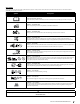
Safety Symbols This page depicts and describes safety symbols that may appear on this product. Read, understand, and follow all instructions on the machine before attempting to assemble and operate. Symbol Description READ THE OPERATOR’S MANUAL(S) Read, understand, and follow all instructions in the manual(s) before attempting to assemble and operate DANGER — ROTATING BLADES Never carry passengers. Never carry children, even with the blades off.
Section 2 — Important Safe Operation Practices Figure 1 line Figure 2 (TOO STEEP) 15°/25% Slope Do not operate machine on slopes in excess of 15 degrees. All slopes require extra caution. If you cannot back up the slope or if you feel uneasy on it, do not mow it. Always mow up and down slopes, never across the face of slopes. WARNING! Slopes are a major factor related to tip-over and roll-over accidents which can result in severe injury or death. To check the slope, proceed as follows: 1.
Assembly & Set-Up 2 Thank You Thank you for purchasing this product. It was carefully engineered to provide excellent performance when properly operated and maintained. Please read this entire manual prior to operating the equipment. It instructs you how to safely and easily set up, operate and maintain your machine. Please be sure that you, and any other persons who will operate the machine, carefully follow the recommended safety practices at all times.
Tools Required • Shipping Brace Removal Adjustable Wrench or Socket Set WARNING Connecting the Battery Cables WARNING California PROPOSITION 65 Battery posts, terminals, and related accessories contain lead and lead compounds, chemicals known to the State of California to cause cancer and reproductive harm. Wash hands after handling. CAUTION When attaching battery cables, always connect the POSITIVE (Red) wire to its terminal first, followed by the NEGATIVE (Black) wire.
Dash Shroud (If Equipped) Tire Pressure There are two shroud types. One shroud for the 1/3/5/K/T-Style and one for the S-Style dash. WARNING Equal tire pressure should be maintained at all times. Refer to the tire sidewall for proper pressure. Continue below for the 1/3/5/K/T-Style, skip ahead to the S-style section for the S-style dash. Fill the fuel tank with gasoline. Use only clean, fresh (no more than 30 days old), unleaded gasoline.
Setting the Deck Gauge Wheels (If Equipped) Attaching the Hood Scoop (If Equipped) Move the tractor to a firm and level surface, preferably pavement, and proceed as follows: 1. 2. Select the height position of the cutting deck by placing the deck lift lever in the normally desired mowing height setting (there are six different cutting height notches on the right fender). Check the deck gauge wheels for contact or excessive clearance with the surface below.
3 Controls & Operation To set the parking brake: Fully depress the parking brake pedal. Move the parking brake lever all the way down and into the parking brake position (PARK BRAKE ON) and then release the brake pedal to allow the parking brake to engage. Hydrostatic Set-Up Ammeter † Throttle/Choke Control Lever Ignition Switch Module To release the parking brake: Depress the brake pedal and the parking brake lever will automatically move out of the parking brake position.
Shift Lever (If Equipped) Ignition Switch Module Deck Lift Lever Foot Control CVT & CVT The lawn tractor will have one of the following ignition switches. Refer to Figure 3-3 to identify which switch your machine utilizes and follow the applicable instructions for proper operation. The deck lift lever is located on the lawn tractor’s right fender. It is used to change the height of the cutting deck. To use, move the lever to the left, then place in the position best suited for your application.
To use the REVERSE CAUTION MODE: Setting the Cutting Height IMPORTANT: The operator MUST be seated in the lawn tractor seat. 1. 1. Start the engine as instructed on page 13. 2. Turn the key from the NORMAL DRIVING MODE (Green) position to the REVERSE CAUTION MODE (Yellow) position of the ignition switch module. See Figure 3-4. Reverse Push Button Indicator Light Reverse Caution Mode Position Normal Driving Mode Stop position Start position 2.
CVT Foot Control CVT Engaging the Blades Engaging the PTO (blade engage) transfers power to the cutting deck. To engage the blades, proceed as follows: 1. Depress the clutch-brake pedal to release the parking brake and let the pedal up. 1. Depress the brake pedal to release the parking brake and let the pedal up. 2. Move the throttle lever into the FAST (rabbit) position. 2. Move the throttle lever into the FAST (rabbit) position. 3.
4 Product Care Maintenance Schedule Before Each use Every 10 Hours Every 25 Hours Every 50 Hours Every 100 Hours P P P P P P Check/Clean Engine Intake Screens & Cooling Fans * Check/Clean Exhaust Manifold, Muffler Pipe & Muffler Shields * Check/Clean Hood/Dash Panel Louvers * Check/Clean Top & Underside of Deck, Under and Around Spindle Covers & Belt Area * Check/Clean Around Fuses, Wiring and Wiring Harnesses * Check/Clean Around Transmission, Axle and Fans * P P P P P P P P P P P P P Clean Hood
One of the best ways to keep your rider running efficiently and to reduce fire risk is to regularly remove debris buildup from the rider. Follow the recommendations below and contact your authorized dealer with any questions. • Debris can accumulate anywhere on the rider, especially on horizontal surfaces. Additional cleaning may be necessary when mowing in dry conditions or when mulching. • Allow the machine to cool in an open area before cleaning.
4. Snap the small end of oil drain sleeve onto the oil sump. See Figure 4-6. 3. Rotate the socket assembly approximately a 1⁄4-turn to align the socket tab with the reflector housing notch; then withdraw the bulb and socket assembly from the reflector housing. See Figure 4-7. • Always keep the rubber boot positioned over the positive terminal to prevent shorting.
Removing the Battery 3. To remove the battery, pull outward and then up on the battery hold-down bracket. See Figure 4-8. Locate the jam nut and lock nut on the front side of the stabilizer bracket. See Figure 4-9 Seat Adjustment Refer to Attaching the Seat in page 8 for seat adjustment instructions. Parking Brake Adjustment WARNING Never attempt to adjust the brakes while the engine is running.
5. Looking at the cutting deck from the left side of the rider, locate the bow-tie pin that secures the deck support rod on the rear left side of the deck. See Figure 4-12. Remove the bow-tie pin that secures the deck support rod, and carefully remove the deck support from the deck lift arm. Tires IMPORTANT: If the cutting edge of the blade has already been sharpened to within 1-5⁄8” from the edge, or if any metal separation is present, replace the blades with new ones. See Figure 4-16.
2. Remove the belt covers by removing the hex washer screws that fasten them to the deck. See Figure 4-17. Hex Washer Screws Spindle Pulley Belt Cover Belt Guard Deck Idler Pulley Figure 4-17 3. It may also be necessary to loosen the hex nut on the left idler pulley to get the belt off the pulley and around the belt guard. 4. Carefully remove the deck belt from around the two spindle pulleys and the two deck idler pulleys. See Figure 4-17. 5.
Medidas de seguridad • Configuración • Funcionamiento • Servicio • Solución de problemas Manual del Operador Tractor cortacésped Índice Medidas de seguridad.................................................. 2 Montaje y Configuración............................................. 7 Controles y Funcionamiento.....................................11 Servicio.........................................................................15 Piezas/Garantía..........
Importantes medidas de seguridad 2 ¡ADVERTENCIA! Este símbolo indica instrucciones de seguridad importantes que, de no seguirse, podrían poner en peligro su seguridad personal y/o su propiedad o la de terceros. Lea y cumpla todas las instrucciones de este manual antes de intentar hacer funcionar esta máquina. Si no respeta estas instrucciones puede provocar lesiones personales.
30. Si se presentan situaciones que no están previstas en este manual, tenga cuidado y use el sentido común. Póngase en contacto con su representante de atención al cliente para obtener ayuda. 7. Funcionamiento en pendiente Las pendientes son uno de los principales factores asociados a los accidentes por pérdida de control y vuelcos que pueden producir lesiones graves o la muerte. Todas las pendientes exigen precaución adicional.
l. m. Nunca guarde la máquina o el recipiente de combustible en un espacio cerrado donde haya fuego, chispas o luz piloto, como por ejemplo de calentadores de agua, calefactores de ambientes, hornos, secadores de ropa u otros aparatos a gas. 8. 9. Deje que la máquina se enfríe por lo menos cinco minutos antes de guardarla. Servicio general 1. 2. 3. 4. 5. 4 Nunca encienda el motor en espacios cerrados o en una zona con poca ventilación.
Símbolos de seguridad En esta página se presentan y describen los símbolos de seguridad que pueden aparecer en este producto. Lea, comprenda y siga todas las instrucciones incluidas en la máquina antes de intentar armarla y hacerla funcionar. Símbolo Descripción LEA LOS MANUALES DEL OPERADOR Lea, entienda y siga todas las instrucciones incluidas en los manuales antes de intentar armarla y hacerla funcionar. PELIGRO — CUCHILLAS GIRATORIASNunca lleve pasajeros.
6 Sección 2 — Importantes medidas de seguridad Figura 1 Línea 15° Slope ¡ADVERTENCIA! Las pendientes son uno de los principales factores asociados a los accidentes por tumbos y vuelcos que pueden producir lesiones graves o la muerte. No utilice la máquina en pendientes de más de 15°. Todas las pendientes exigen precaución adicional. Si no puede retroceder por la pendiente o si no se siente seguro, no realice ningún corte.
Montaje y Configuración 2 Muchas gracias Gracias por comprar este producto. Ha sido cuidadosamente diseñado para brindar excelente rendimiento si se lo hace funcionar y se lo mantiene correctamente. Por favor lea todo este manual antes de hacer funcionar el equipo. El manual le indica cómo configurar, hacer funcionar y mantener la máquina de manera fácil y segura.
Herramientas necesarias • Extracción de la traba de seguridad Llave ajustable o juego de llaves de vaso Conexión de los cables de la batería ADVERTENCIA PROPOSICIÓN 65 de California: Los bornes y contactos de la batería, y los accesorios afines contienen plomo y compuestos de plomo, sustancias químicas que el Estado de California considera que pueden producir cáncer y daños en el sistema reproductivo. Lávese las manos después de estar en contacto con estos componentes. 3.
asiento (b). Deslice el asiento (b) hacia adelante o hacia atrás, según lo desee. Vuelva a colocar la perilla de ajuste (a). Consulte la Figura 2-6. Cubierta de instrumentos (si está equipado) Hay dos ipos de velo. Una cubierta para el / / T-Estilo 1/3/5 K y otro para el salpicadero S-Style. Continuar por debajo de 1/3/5 / K / T-Style, salte a la sección S-estilo para el tablero de estilo S. espacio uniforme entre la campana (g) y la cubierta guión (a). Vea la Figura 2-8. 4.
3. Vuelva a colocar la tapa del combustible. IMPORTANTE: No llene en exceso el depósito de combustible. Llene el depósito no más de 1⁄2” por debajo de la base del cuello de llenado dejando espacio para la expansión del combustible. Consulte la Figura 2-10. STOP ¡PARE! Continúe a Ajuste de las ruedas de calibración de la plataforma (si está equipado) en la página 30.
Controles y Funcionamiento 3 Configuración Hidrostática Amperímetro † Palanca de control del acelerador/cebador Módulo del interruptor de contacto Para sacar el freno de mano: Presione el pedal de freno y la palanca del freno de mano automáticamente saldrá de la posición del freno de mano. Palanca del freno de mano /Control de velocidad † Pedal de freno †/Pedal de embrague-freno † Pedal de CVT y CVT Para poner el freno de mano: Presione totalmente el pedal del freno.
Palanca de cambios (si está equipada) Módulo del interruptor de contacto Palanca de elevación de la plataforma Pedal de CVT y CVT El tractor cortacésped tendrá uno de los siguientes interruptores de contacto. Consulte la Figura 3-3 para identificar qué interruptor utiliza su máquina y siga estas instrucciones para un funcionamiento adecuado. La palanca de elevación de la plataforma se encuentra sobre el guardabarros derecho del tractor cortacésped.
Para utilizar el MODO PRECAUCIÓN MARCHA ATRÁS: Ajuste de la altura de corte IMPORTANTE: El operador DEBE estar sentado en el asiento del tractor cortacésped. 1. 1. Ponga en marcha el motor como se indica en la página 13. 2. Gire la llave desde la posición MODO MARCHA NORMAL (verde) hasta la posición de MODO PRECAUCIÓN MARCHA ATRÁS (amarillo) del módulo del interruptor de contacto. Consulte la Figura 3-4. 2.
CVT Pedal de CVT Enganche de las cuchillas Al conectar la PTO (enganche de cuchillas) se suministra energía a la plataforma de corte. Para enganchar las cuchillas, haga lo siguiente: 1. Presione el pedal de embrague-freno para liberar el freno de mano y deje que suba el pedal. 1. Presione el pedal de freno para liberar el freno de mano y deje que suba el pedal. 2. Mueva la palanca del acelerador a la posición RÁPIDO (liebre). 2. Mueva la palanca del acelerador a la posición RÁPIDO (liebre). 3.
Cuidado del producto 4 Programa de mantenimiento Antes de cada uso Compruebe/Limpie las Pantallas de Entrada de Motor y los Ventiladores de Enfriamiento * Revisar/Limpiar el Colector de Escape, el Silenciador y los Escudos del Silenciador * Compruebe/Limpie la Campana/Tablero Tableros * Compruebe/Limpie la parte superior y la parte inferior de la cubierta, debajo y alrededor de las cubiertas del eje y el área de la correa * Comprobar / limpiar alrededor de los fusibles, el cableado y los arneses de cable
Limpieza del tractor • Limpia alrededor y cerca de la transmisión, el eje y el área del ventilador. Vea la Figura 4-4. ADVERTENCIA Para realizar el cambio de aceite, proceda de la siguiente manera: 1. Deje el motor funcionando durante algunos minutos para que el aceite del cárter se caliente. El aceite caliente fluirá más libremente y arrastrará más sedimentos del motor que se puedan haber depositado en el fondo del cárter. Tenga cuidado y evite quemarse con el aceite caliente. 2.
1. 2. 3. 4. Deje el motor funcionando durante algunos minutos para que el aceite del cárter se caliente. El aceite caliente fluirá más libremente y arrastrará más sedimentos del motor que se puedan haber depositado en el fondo del cárter. Tenga cuidado y evite quemarse con el aceite caliente. Abra el capó del tractor y ubique el orificio de drenaje de aceite del lado izquierdo del motor. Desenrosque el tapón de llenado de aceite y extraiga la varilla de nivel de aceite del tubo de llenado.
4. Haga la conexión final al bloque del motor del tractor, alejado de la batería. Acople a una parte sin pintura para garantizar una buena conexión. 1. Con el tractor estacionado sobre una superficie firme y nivelada, coloque la palanca de elevación de la plataforma en la segunda muesca antes de la superior (segunda posición más elevada) y rote la cuchilla lo más cerca del canal de descarga que está paralelo al tractor. 2.
5. Mirando la plataforma de corte desde el lado izquierdo del tractor, ubique el pasador de chaveta que sujeta la varilla de soporte de la plataforma del lado posterior izquierdo de la plataforma. Consulte la Figura 4-12. Extraiga el pasador de chaveta que sujeta la varilla de soporte de la plataforma, y con cuidado saque el soporte de la plataforma del brazo de elevación de la plataforma. 10.
2. Extraiga las cubiertas de la correa retirando los tornillos con arandela hexagonales que las sujetan a la plataforma. Consulte la Figura 4-17. Pase la correa alrededor de las dos poleas locas de la plataforma, como se ve en la Figura 4-17. 7. Vuelva a apretar la tuerca hexagonal de la polea loca izquierda aflojada en el paso 3. Polea del husillo 8. Protección de Cubierta de la la correa correa Vuelva a montar las cubiertas de la correa que se retiraron en el paso 2. 9.