
Operating Guide

18 Section 4 — Product care
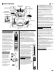
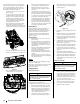
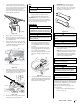
Removing the Battery
To remove the battery, pull outward and then up
on the battery hold-down bracket. See Figure 4-8.
Figure 4-8
Fuse
One 20A fuse is installed in your rider’s wiring
harness to protect the rider’s electrical system
from damage caused by excessive amperage.
If the electrical system does not function, or your
rider’s engine will not crank, check that the fuse
has not blown. It can be found at the rear of the
unit, underneath the fender located by the battery.
WARNING
Always use a fuse with the same amperage capacity for
replacement.
Leveling the Deck
NOTE: Check the rider’s tire pressure before
performing any deck leveling adjustments. Refer
to Tires on page 19 for more information
regarding tire pressure.
Front-to- Rear
The front of the cutting deck is supported by a
stabilizer bar that can be adjusted to level the deck
from front to rear. The front of the deck should
be between ¼” and ⁄” lower than the rear of the
deck. Adjust if necessary as follows:
1. With the rider parked on a firm, level
surface, place the lever for lifting the
platform on the second to the top notch
(second highest position) and rotate the
blade as close to the discharge channel that
is parallel to the rider.
2. Measure the distance from the front of
the blade tip to the ground and the rear
of the blade tip to the ground. The first
measurement taken should be between ¼”
and ⁄” less than the second measurement.
Determine the approximate distance
necessary for proper adjustment and
proceed, if necessary, to the next step.
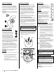
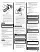
3. Locate the jam nut and lock nut on the front
side of the stabilizer bracket. See Figure 4-9
Figure 4-9
4. After loosening the jam nut:
• Tighten the lock nut to raise the
front of the deck;
• Loosen the lock nut to lower the
front of the deck.
4. Retighten the jam nut loosened earlier
when proper adjustment is achieved.
Side-to-Side
If the cutting deck appears to be mowing
unevenly, a side-to-side adjustment can be
performed. Adjust if necessary as follows:
1. With the rider parked on a firm, level
surface, place the deck lift lever in the
second notch from the top (second highest
position) and rotate both blades so that they
are perpendicular with the rider.
2. Measure the distance from the outside of
the left blade tip to the ground and the
distance from the outside of the right blade
tip to the ground. Both measurements taken
should be equal. If they’re not, proceed to
the next step.
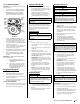
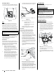
3. Loosen, but do NOT remove, the hex cap
screw on the left deck hanger bracket. See
Figure 4-10.
Hex Cap Screw
Figure 4-10
4. Balance the deck by using a wrench to turn
the adjustment gear (found immediately
behind the hex cap screw just loosened)
clockwise/up or counter-clockwise/down. The
deck is properly balanced when both blade tip
measurements taken earlier are equal.
5. Retighten the hex cap screw on the left deck
hanger bracket when proper adjustment is
achieved.
Seat Adjustment
Refer to Attaching the Seat in page 8 for seat
adjustment instructions.
Parking Brake Adjustment
WARNING
Never attempt to adjust the brakes while the engine is
running. Always disengage PTO, move shift lever into
neutral position, stop engine and remove key to prevent
unintended starting.
If the rider does not come to a complete stop
when the brake pedal is completely depressed, or
if the rider’s rear wheels can roll with the parking
brake applied, the brake is in need of adjustment.
See an authorized service dealer to have your
brakes properly adjusted.
Cutting Deck Removal
To remove the cutting deck, proceed as follows:
1. Place the PTO lever in the disengaged (OFF)
position and engage the parking brake.
2. Lower the deck by moving the deck lift lever
into the bottom notch on the right fender.
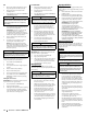
3. Remove the belt-keeper rod, from around
the rider’s engine pulley, by removing the
self-tapping screw (A) that secures it. See
Figure 4 -11.
A
B
C
Figure 4-11
NOTE: Make a note what hole the other
end of the belt-keeper rod is inserted in for
reinstallation purposes.
4. Remove the belt (C) from around the rider’s
engine pulley and idler pulley(s). See Figure
4-11.