Safe Operation Practices • Set-Up • Operation • Maintenance • Service • Troubleshooting • Warranty Operator’s Manual Three-Stage Snow Thrower Attachment — 19A40024OEM WARNING READ AND FOLLOW ALL SAFETY RULES AND INSTRUCTIONS IN THIS MANUAL BEFORE ATTEMPTING TO OPERATE THIS MACHINE. FAILURE TO COMPLY WITH THESE INSTRUCTIONS MAY RESULT IN PERSONAL INJURY. MTD LLC, P.O. BOX 361131 CLEVELAND, OHIO 44136-0019 Printed In USA Form No.
1 To The Owner Thank You Thank you for purchasing an MTD snow thrower attachment. It was carefully engineered to provide excellent performance when properly operated and maintained. Please read this entire manual prior to operating the equipment. It instructs you how to safely and easily set up, operate and maintain your machine. Please be sure that you, and any other persons who will operate the machine, carefully follow the recommended safety practices at all times.
Important Safe Operation Practices 2 WARNING! This symbol points out important safety instructions which, if not followed, could endanger the personal safety and/or property of yourself and others. Read and follow all instructions in this manual before attempting to operate this machine. Failure to comply with these instructions may result in personal injury. When you see this symbol.
8. 4. Do not operate machine while under the influence of alcohol or drugs. 5. Muffler and engine become hot and can cause a burn. Do not touch. 6. Exercise extreme caution when operating on or crossing gravel surfaces. Stay alert for hidden hazards or traffic. Do not carry passengers. 7. Exercise caution when changing direction and while operating on slopes. 8. Do not clear snow across the face of slopes; go up and down. Exercise extreme caution when operating on slopes.
Clearing A Clogged Discharge Chute 5. Snow thrower shave plates and skid shoes are subject to wear and damage. For your safety protection, frequently check all components and replace with original equipment manufacturer’s (O.E.M.) parts only. “Use of parts which do not meet the original equipment specifications may lead to improper performance and compromise safety!” 6. Check clutch controls periodically to verify they engage and disengage properly and adjust, if necessary.
3 Assembly & Set-Up Model 19A40024OEM three-stage snow thrower attachment is designed for use with select lawn tractors and garden tractors. Refer to your tractor’s Operator’s Manual to assure compatibility. Carton Contents Before beginning installation, remove all parts from the carton to make sure everything is present. Carton contents are listed below and shown on page 6 and 7. The hardware pack contains seven individual bags of hardware.
Auger Housing Assembly Chute Crank/ Chute Assembly Bumper Belt Keeper Rod Chute Ring Lift Handle Assembly Lock Rods Carriage Assembly 5” Extension Spring Carriage Support Brackets Frame Rail Assembly 51⁄2” Extension Spring Wireform S-Hook Section 3 — Assembly & Set-Up 7
WARNING! Before installing the attachment, place tractor on a firm and level surface. Place the PTO in the disengaged (OFF) position, set the parking brake, shut engine off and remove key to prevent unintended starting. 2. Secure the right carriage support bracket marked with an “R” to the outside of the tractor’s frame with three hex screws and flange lock nuts as shown in Figure 3-2.
2. Remove the rod from the rear of the carriage assembly. Retain the clips and rod, as they will be reattached in later steps. See Figure 3-4. 4. Figure 3-4 3. If your tractor is equipped with a Manual PTO, attach the 5” extension spring to the carriage idler bracket as show in Figure 3-5. If your tractor is equipped with a Electric PTO, attach the 512” extension spring to the wireform S-hook and then to the carriage idler bracket as show in Figure 3-6. Figure 3-6 5.
8. Secure the carriage in place with the two lock rods. See Figure 3-8. Figure 3-10 Figure 3-8 9. and pivot the pulley outward. If your tractor is equipped with a Manual PTO, and the belt keeper rod wasn’t removed from the tractor when the deck was taken off, remove it before proceding to the next step. See Figure 3-9. 11. On models with a Manual PTO, install the new belt keeper rod and secure it with the hex screw retained when the old keeper rod was removed. See Figure 3-11.
12. On models with a Manual PTO, attach the PTO cable to the idler bracket as show in Figure 3-12. NOTE: Secure the cable in place with the same pin that secured the cable to the mowing deck. 3. Route the auger assembly’s belt around the rail assembly’s idler pulleys as shown in Figure 3-14. Important: Make certain that the flat side of the belt is positioned on the flat pulley, and the V side of the belt is positioned on the V-Pulleys.
Attaching the Chute Crank Assembly 2. Use Hardware Bag 689-00353 to attach the chute crank assembly. NOTE: Make sure the groove found in the chute ring is facing forward. NOTE: Having an assistant support and position the chute crank assembly will aid in completing the following step. 1. Position the chute ring on top of the auger housing’s chute adapter as show in Figure 3-16. Using a 9⁄16” wrench, secure the chute crank assembly to the auger housing assembly with four flange lock nuts.
4. Using two 7⁄16” wrenches, secure the chute assembly to the chute ring with three flange keepers, six hex screws and flange nuts as show in Figure 3-18. Important: Do not over-tighten the flange keeper hardware. Doing so may result in the chute binding during rotation. Attaching the Lift Handle Assembly Use Hardware Bag 689-00355 to attach the lift handle assembly. NOTE: Having an assistant support and position the lift handle assembly will aid in completing the following step. 1.
3. Pull the cable outward to take up slack, and tighten the jam nuts to secure the cable housing to the lift handle. See Figure 3-22. NOTE: Supporting the end of rail assembly with a 4x4 block of wood (beneath both rails) will aid in completing the following step. 2. Pivot the rear of the frame rail assembly upward and secure it to the inside of the carriage assembly with the clevis pins and hairpin clips removed earlier. See Figure 3-24.
5. Repeat the previous step on the left side of the auger housing. 6. Route the auger assembly’s belt around the carriage spindle pulley as shown in Figure 3-26. NOTE: To relieve tension on the idler pulleys, insert a ratchet with a 3⁄8” drive into the square hole on the idler bracket and pivot it outward. Set-Up Shear Pins Two pairs of replacement auger shear pins and bow tie cotter pins are included with your snow thrower in Hardware Bag 689-00356. Store them in a safe place until needed.
4 Controls Trigger Control Chute Directional Control Lift Handle Chute Directional Control Controls WARNING! Be familiar with all controls and their proper operation. Know how to stop the machine and disengage them quickly. Lift Handle The lift handle is located on the right side of the tractor and is used to raise and lower the snow thrower attachment. 16 1.
5 Operation Operation WARNING! Read, understand, and follow all instructions and warnings on the tractor, the attachment, and in the operator’s manuals before operating. Your snow thrower attachment is capable of displacing snow and clearing a path a width of 42 inches. 13. NEVER drive the tractor into a snow bank. The snow thrower attachment is not a dozer plow. The lift linkage and/or the snow thrower drive system can be damaged as a result of “plowing” with the snow thrower attachment. 14.
Replacing Shear Pins Tire Chain Kits The augers are secured to the spiral shafts with six shear pins and cotter pins. If the auger should strike a foreign object or ice jam, the snow thrower is designed so that the pins may shear. If the augers will not turn, check to see if the pins have sheared. See Figure 5-1. • 20” x 8.00” tires 490-241-0023 • 20” x 10.00” & 20” x 9.00 tires 490-241-0024 • 22” x 9.50” & 23” x 9.50” tires 490-241-0025 • 23” x 10.
6 Maintenance WARNING: Before lubricating, repairing, or inspecting, place tractor on a firm and level surface. Place the PTO in the disengaged (OFF) position, set the parking brake, shut engine off, and remove key to prevent unintended starting. Cleaning the Tractor Always clear the engine and hood of snow after each use and prior to storing. Lubricating the Chute Directional Control Lubricating the Auger Shaft At least once a season, remove the shear bolts from the auger shafts.
Off-season Storage To remove the snow thrower attachment from the tractor, refer to the images found in the Set-up and Assembly section of this manual and follow the steps below: WARNING: Before removing the snow attachment, place the tractor on a firm and level surface. Place the PTO in the disengaged (off) position, set the parking brake, shut engine off and remove key to prevent unintended starting. Important: Store all hardware (e.g. clevis pins, hair pin clips, etc.
Notes 7 21
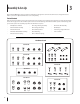
Model 19A40024OEM 70 77 72 74 66 17 59 73 69 67 63 71 71 75 2 49 62 49 61 60 58 57 54 48 60 51 60 50 53 52 55 60 56 71 76 68 56 3 57 53 36 15 41 9 17 19 27 22 26 34 46 38 34 23 20 24 14 31 6 20 23 34 38 38 4 20 26 27 46 39 22 65 62 64 80 81 78 17 71 18 43 18 16 35 1 37 47 30 17 7 12 28 45 17 25 38 9 68 10 13 44 29 38 4 42 6 20 21 2 20 22 29 34 38 38 5 29 11 9 40 25 38 20 8 34 5 79 32 33 17 42
Model 19A40024OEM Ref No. Part Number Ref No. Part Number 1 05931A Housing, Bearing, 1.85 ID 41 750-06184 Spacer, .385Id x 1.75 OD x .585 2 918-07032 Gearbox Assembly, Auger, 42” 42 750-06261 Spacer, .76Id x 1.25 OD x 1.81 Lg 3 731-2635 931-2643 Cleanout Tool Mount Cleanout Tool 43 756-0627D Pulley, Idler, 3.50 Dia.
Model 19A40024OEM 11 14 6 17 17 16 20 4 23 22 18 15 3 7 2 10 6 13 24 13 21 24 6 21 5 8 19 1 12 9
Model 19A40024OEM Ref No. Part Number 1 603-0302A-0637 Assembly, Chute Tilt Bracket 2 611-05064 Control Assembly 3 684-05094-0637 Bracket Assembly 4 710-0487 Screw, Carriage, 5/16-18, 2.00, Gr5 5 710-05050 Bolt, Eye, 5/16-18 x 3.25 6 712-04063 Nut, Flange Lock, 5/16-18, Grf, Nylon 7 912-3010 Nut, Hex, 5/16-18, Gr5 8 914-0101 Pin, Cotter, Int .08 x 1.42 9 915-0138 Pin, Roll, 1/8 OD, .63 10 715-04095 Pin, Spg, .156 Dia x .
Model 19A40024OEM 7 14 24 15 4 1 28 3 21 17 10 13 22 24 25 19 10 16 10 12 28 2 23 11 18 6 23 9 19 18 12 5 10 1 10 10 9 6 26 27 10 10 22 17 21 26 20 8
Model 19A40024OEM Ref No. Part Number 1 618-07034 Link Assembly, Lift — 711-06143A Ferrule, .510 x .496 — 712-05046 Hex Nut, 1/2-13 — 747-06384 Lift Link 2 683-05156-0637 Bumper Assembly 3 684-05084 Shft Assembly, Lift 4 684-05085-0637 Handle Assembly, Lift 5 710-04095 Hex Screw, 3/8-16, 1.00, Gr5 6 710-1315 Screw, Self-tapping, 3/8-16, 1.25 7 710-1625 Screw, Oval, #10-24 x 1.75 8 710-3118 Hex Screw, 3/8-16, 1.00, Gr5, Lock 9 711-0396 Spacer, .385 x .623 x .
Model 19A40024OEM 39 39 37 38 21 2 38 21 38 39 3 40 13 13 27 29 39 37 22 18 35 31 23 20 7 38 10 16 26 14 10 15 9 1 36 28 11 6 15 12 12 25 8 5 24 5 17 13 27 13 22 32 13 13 33 32 7 20 30 19 4 34 6 28 29 31 13 14 26
Model 19A40024OEM Ref No. Part Number 1 N/A Spindle Assembly, Pulley, 7.25 Dia — 918-07070 Spindle Housing — 684-05082-0637 Spindle Hanger Bracket — 710-1260A Hex Washer Screw, 5/16-18 x .750 2 684-05077-0637 Bracket Assembly, Hanger, Right 3 684-05078-0637 Bracket Assembly, Hanger, Left 4 710-0347 Hex Screw, 3/8-16, 1.75, Gr5, Std 5 710-3001 Hex Screw, 3/8-16, .880, Gr5, Std 6 710-3005 Hex Screw, 3/8-16, 1.25, Gr5, Std 7 710-3144 Hex Screw, 3/8-16, 2.
Model 19A40024OEM 7 19 B 17 22 15 17 B 14 7 14 17 1 25 19 5 11 4 2 8 12 9 13 21 23 27 24 8 8 3 8 27 6 26 18 8 20 B 10 A 12 A 16 30 B 21 13
Model 19A40024OEM Ref No. Part Number 1 603-05172-0637 Bracket Assembly, Supt, Spndl 2 684-05080-0637 Bracket Assembly, Frm, RH 3 684-05081-0637 Bracket Assembly, Frm, LH 4 710-05023 Bolt, Shoulder, Hex Hd 5 710-0923 Hex Screw, 5/8-18, 3.00, Gr5, Std 6 710-1245B Hex Screw, 5/16-24, .875, Gr8, Lock 7 710-1652 Screw, Self-tapping, 1/4-20 x .625 8 710-3001 Hex Screw, 3/8-16, .880, Gr5, Std 9 711-06298 Shaft, Supt, Mule Idler 10 711-06303 Shaft, .375Od x 12.
MANUFACTURER’S LIMITED WARRANTY FOR The limited warranty set forth below is given by MTD LLC with respect to new merchandise purchased and used in the United States and/or its territories and possessions, and by MTD Products Limited with respect to new merchandise purchased and used in Canada and/or its territories and possessions (either entity respectively, “MTD”). b.